Powered by Safety
®
7
Equipment Description
01.4IB.48041
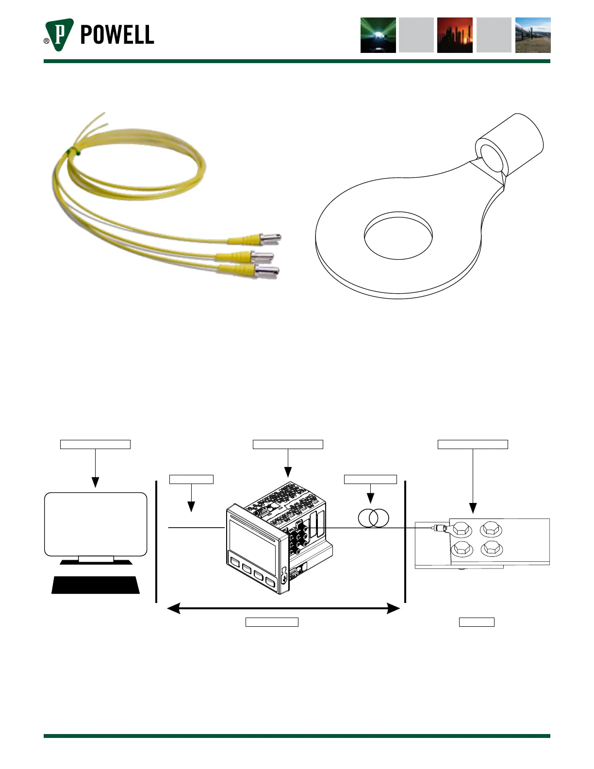
Figure 2 Fiber-Optic Probe
3. The probe mounting fixtures are available
in several sizes, all of which provide the
physical contact between the probe and
the LOI. It is important that the fixture be
connected securely, in order to provide
robust thermal contact and accurate
measurements.
Figure 3 Ring-Style Mounting Fixture
5. Once installed, the three primary
components look schematically as shown in
Figure 4.
Figure 4 BriteSpot® Plus System Overview
1. SUPERVISORY SYSTEM
NON-ENERGIZED ENERGIZED
COM & POWER
2. CONVERSION MODULE
FIBER OPTIC PROBE
3. MOUNTING FIXTURE