Powered by Safety
®
24
Installation
01.4IB.48041
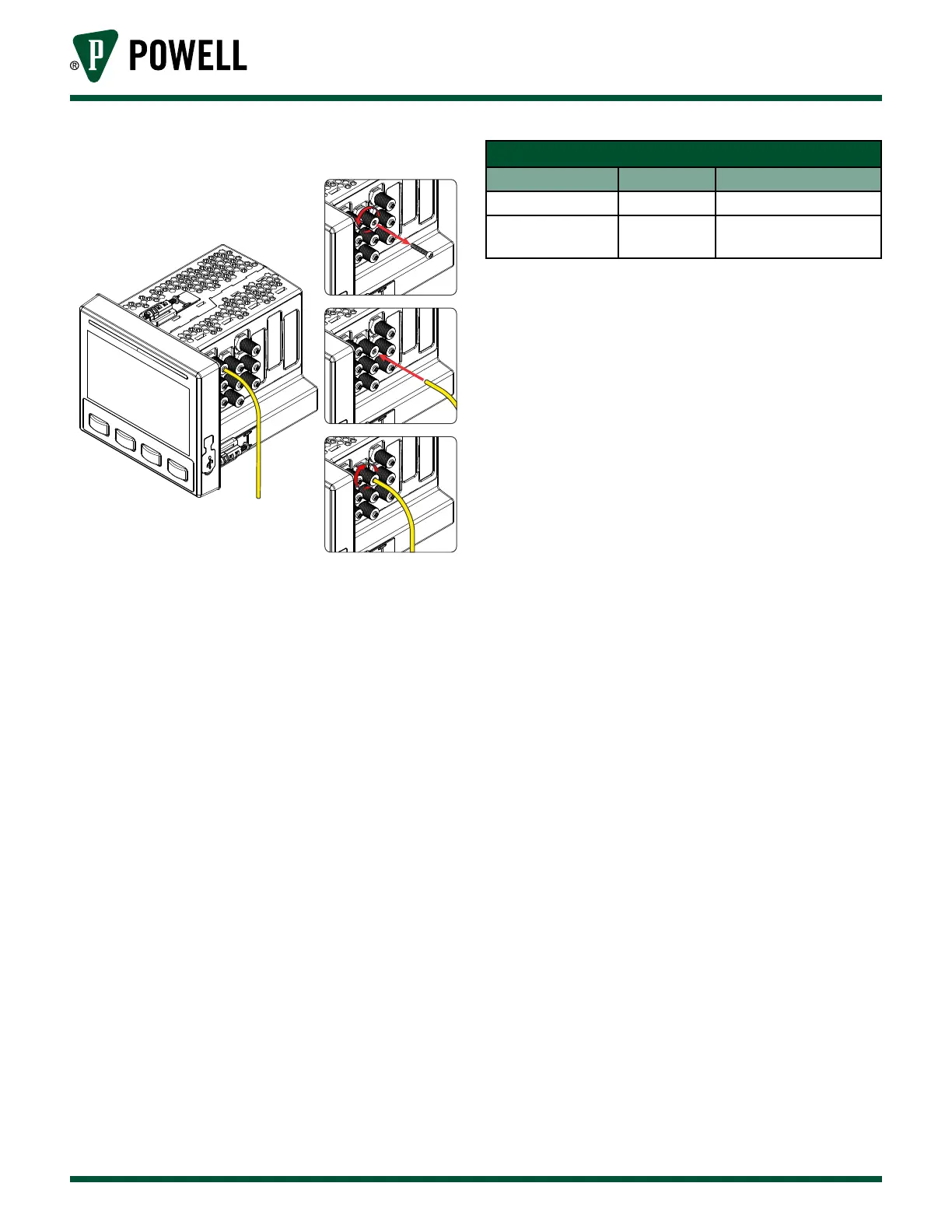
BriteSpot® Plus
Figure 27 Fiber Installation
d. Ensure the Optical Signal is adequate
once all the fibers are installed and
connected. They must be check to
ensure the optical signal is strong
enough for proper operation of the
device.
i. Apply power to the device and wait
several minutes for all probes to
stabilize.
ii. For each probe, look at the color of
the BriteSpot® Status LED and follow
the actions recommended in Table D
BriteSpot Status LED Colors.
Table D BriteSpot® Plus Status LED Colors
Status LED Color Status Action
Green Ok No Action
Red Fail
Trim several mm o
ber end & re-insert
iii. Complete the procedure by
checking the fiber power for the
remaining probes, this can be read
on the BriteSpot Plus status web
page or the BriteSpot information
screen. Fiber power must be 7, 8, 9,
or 10 (strongest signal)
iv. If any of the probes continue to
fail, see Ch 6 Troubleshooting for
remedial actions.