Powered by Safety
®
37
Usage
01.4IB.48041
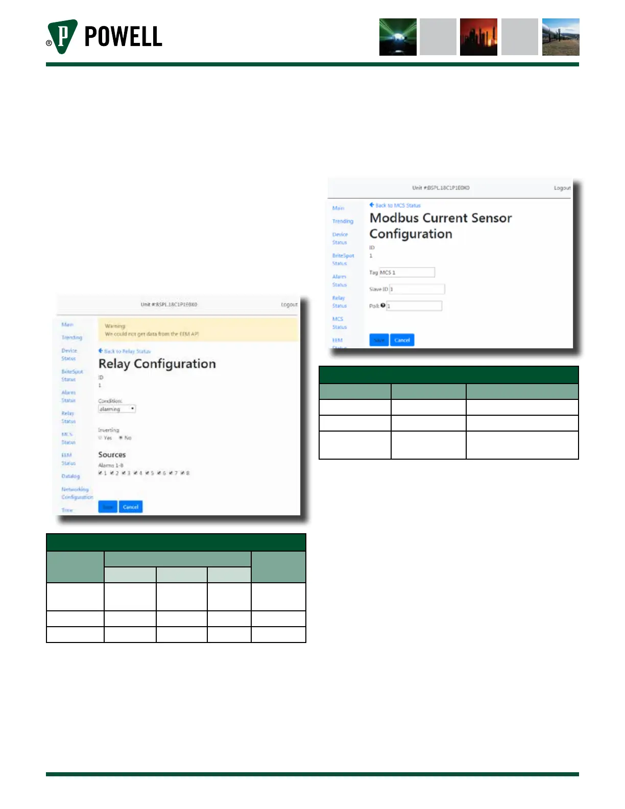
viii. Relay Configuration
The relay configuration pages
(Figure 48) can be accessed directly
from the main page or by clicking
“Relay Status” followed by the
associated relay ID. It allows the
user to configure when one of the
control relays will actuate and what
alarm sources to base that decision
on.
Figure 48 Relay Configuration Web Page
Table N Relay Configuration Web Page
Parameter
Default Value
Range/
Options
RLY 1 RLY 2 RLY 3
Condition Warning Alarming -
Warning/
Alarming
Inverting No No No Yes/No
Sources Alm 1 Alm 1 None Alarms 1-8
ix. MCS Configuration
The MCS configuration page
(Figure 49) is reached by navigating
to “MCS Status” and clicking on the
desired MCS ID. The page allows
the user to connect to a MCS by
entering its slave ID as well as
change the tag and polling rate.
Figure 49 MCS Configuration Web Page
Table O MCS Configuration Web Page
Parameter Default Value Range/Options
Tag MCS x 32 Characters
Slave ID 0 0 = disabled, 1-247
Poll 15 s
0 = disabled, any integer
number of seconds
Note: MCS devices must be configured with
a baud rate of 19200 to communicate
with the BriteSpot® Plus.
x. EcoVisor™ Configuration
The EcoVisor configuration page
(Figure 50) is reached by navigating
to “EcoVisor Status” and clicking on
the desired EcoVisor ID. This page
allows the user to connect to an
EcoVisor by entering its slave ID as
well as change the tag and polling
rate.