Powered by Safety
®
40
Usage
01.4IB.48041
BriteSpot® Plus
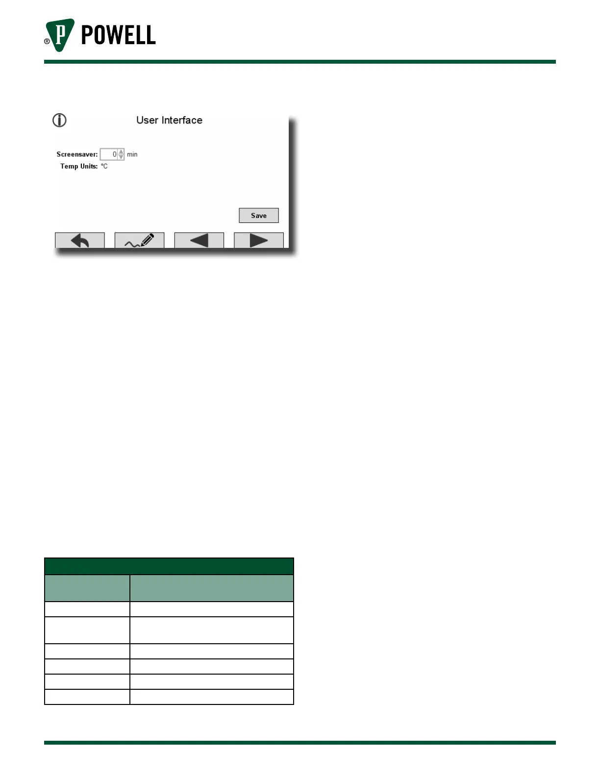
Figure 56 User Interface Settings Screen
c. SpeciAl reGiSterS
The following details the interpretation of
information that can be obtained from the
BriteSpot® Plus through the MODBUS RTU or
MODBUS TCP interfaces. There are several
special register types that warrant particular
attention when polling the BriteSpot Plus:
1) BriteSpot® Plus Status Registers Interpretation
The status registers provide a generic set
of status codes for each BriteSpot channel
independently. These codes
(Table S BriteSpot® Status Register Codes) can
identify one of several problems that may
need to be rectified. In general, the status
registers provide more detailed description
when problems arise. The status registers
can be accessed via MODBUS (Appendix D).
Table S BriteSpot® Status Register Codes
Status Register
Value
Description
0 No Errors
1
Optical Probe Not Detected
(broken or not connected)
2 Optical Signal Too Weak
4 Temperature Out of Range
8 BriteSpot Module is Still Initializing
0x7FFF BriteSpot Module Error
2) Alarm Registers
The BriteSpot Plus alarms have 18
associated registers, which are described
in the MODBUS memory map (Appendix
D). The first six registers indicate alarm
type, whether the alarm is latching or not,
warning on/off thresholds and alarm on/
off thresholds. Each alarm on the BriteSpot
Plus conversion module is equipped with
four 16 bit registers to indicate which
sources contribute to that alarm and eight
16 bit registers that are used to indicate
that one or more of the selected alarm
sources has exceeded the warning or
alarm thresholds. Each of these sets of four
registers (64 bits) represents a bit-mask that
indicates what the sources of a warning or
alarm are. In some cases, users may prefer
to just monitor these registers and take
action if they become active.
a. Alarm Source Bit-Mask
Alarm sources are represented using a
64 bit-mask (see Table T and Table U).