Powered by Safety
®
49
Appendix B
01.4IB.48041
Appendix B COM Cards (COM1)
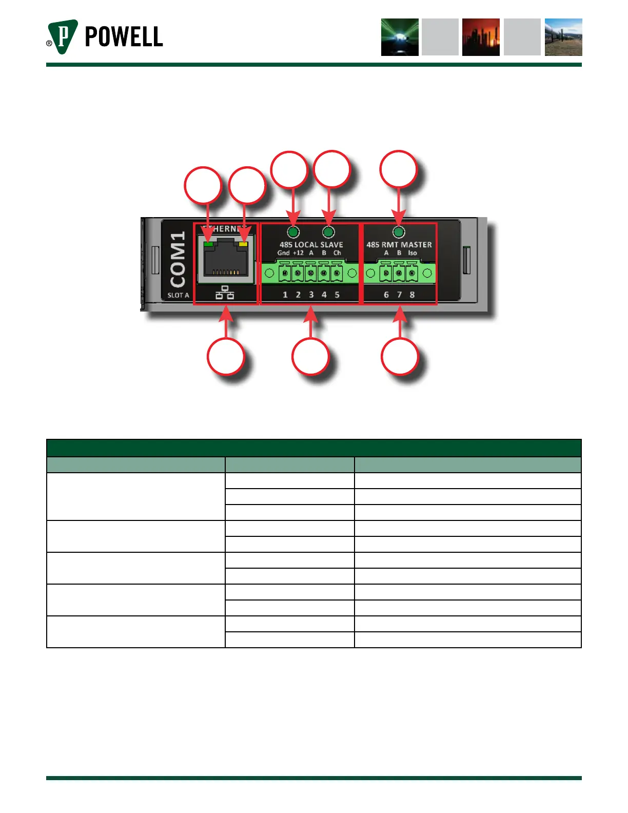
Figure 66 COM Card 1
a.
b.
c.
d.
e.
f.
g.
h.
Figure 66 shows COM card 1, and highlights the various port and indicators. There are five indicator LEDs
on COM 1. The meaning of the indicator LEDs is explained below.
Table X COM 1 Indicator LEDs
Indicator LED Color Meaning
(d) Ethernet Link
Flashing Green Ethernet Trac
Green Connection Established
O No Connection Established
(e) Ethernet 10/100
Orange 100 Mbit Mode
O 10 Mbit Mode
(f) Auxiliary Power
Green Auxiliary 12V Available
O Auxiliary 12V Unavailable
(g) 485 Local Slave
Flashing Green Receiving Data
Flashing Red Transmitting Data
(h) RMT Master
Flashing Green Receiving Data
Flashing Red Transmitting Data
COM 1 has 3 interface ports with various applications.
a. Ethernet Port: MODBUS TCP, Web Interface
b. Terminals 1-5: RS-485, 2 wire, MODBUS, Interface to MODBUS Current Sensor (MCS) or other
Powell slave devices. For more information, refer to the Modbus Current Sensor Instruction
bulletin located at powellind.com.
c. Terminals 6-8: RS-485, 2 wire, MODBUS, Interface to RS-485 Network