Powered by Safety
®
14
Installation
01.4IB.48041
BriteSpot® Plus
Once the fixture has been put in place, follow
the manufacturer’s recommended torque
setting for the original hardware.
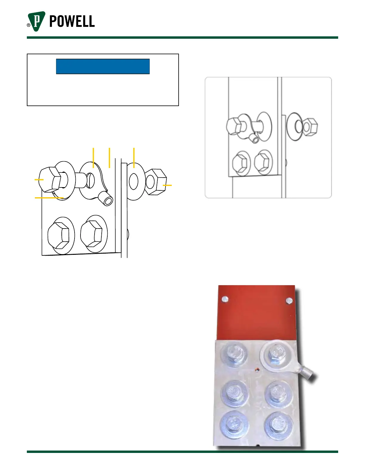
Figure 9 Installation Sequence of Lug with
Standard Washers
a b c
d
e
f
a. Lug
b. Measurement Surface
c. Washer
d. Bolt
e. Nut
F. Washer
Figure 10 Installation Sequence of Lug with
Belleville Washers
4. Once the lug is mounted, the probe can
be installed. This is done by inserting the
probe tip into the end of the lug. Ensure
that the head of the “probe-lock” set screw
is visible and easily accessible to allow it to
be secured.
Figure 11 Mounting Lug