Powered by Safety
®
17
Installation
01.4IB.48041
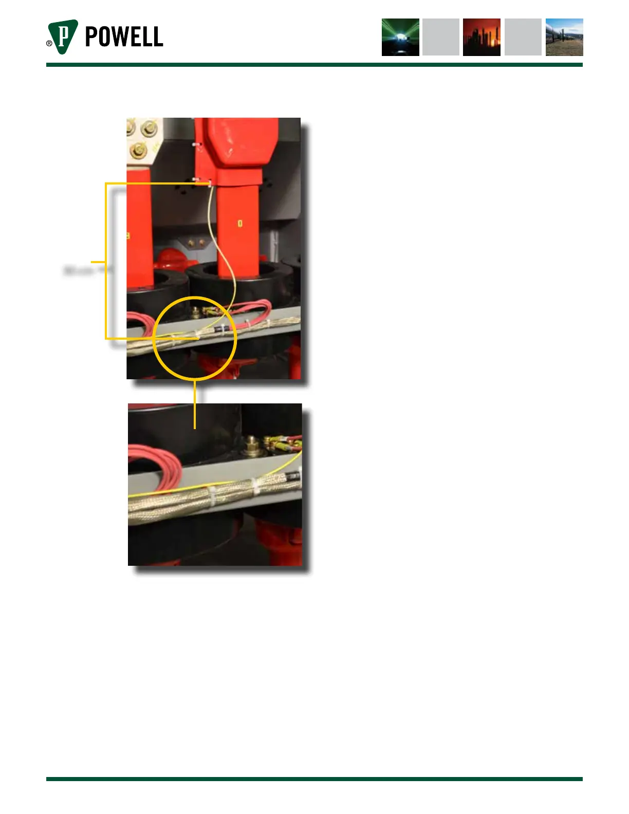
Figure 18 Safe Dielectric Routing Practices
30 cm
Do not straddle phases with the fiber. The
fiber must go from the LOI to any non-
energized contact point and then to the
BriteSpot® Plus conversion module. See
Figure 17.
3. Mark each end of the fiber with a means
to identify each fiber when finalizing the
installation. If this is not done, it can be
very challenging to correlate installation
location with the fiber. Black marker and
tape are acceptable, as are approved wire
markers (preferred). Ensure that all marking
are a safe distance from the energized end,
typically this is 60-100 cm (2-3 ft).
d. mount tHe BriteSpot® pluS converSion module
The BriteSpot Plus conversion module provides
the power, telemetry, and user interface to
the sensors. Once installed, the BriteSpot
Plus conversion module can be configured
to provide a wide range of features through
the Ethernet and serial ports. In addition to
proximity to the LOI, thought should also be
given to ensuring that there is access to the
user interface of the BriteSpot Plus conversion
module following installation. This is needed
for initial configuration and retrieval of
onboard logged data.
1) Insert BriteSpot Plus Through Mounting Hole
The BriteSpot Plus conversion module
requires a ¼ DIN panel mounting cutout.
The dimensions of this cutout, as well as full
dimensions of the various configurations
can be found in Appendix A.
Ensure the mounting gasket is in place,
then slide the body of the BriteSpot Plus
conversion module through the panel
cutout as shown in Figure 19.