Powered by Safety
®
34
Usage
01.4IB.48041
BriteSpot® Plus
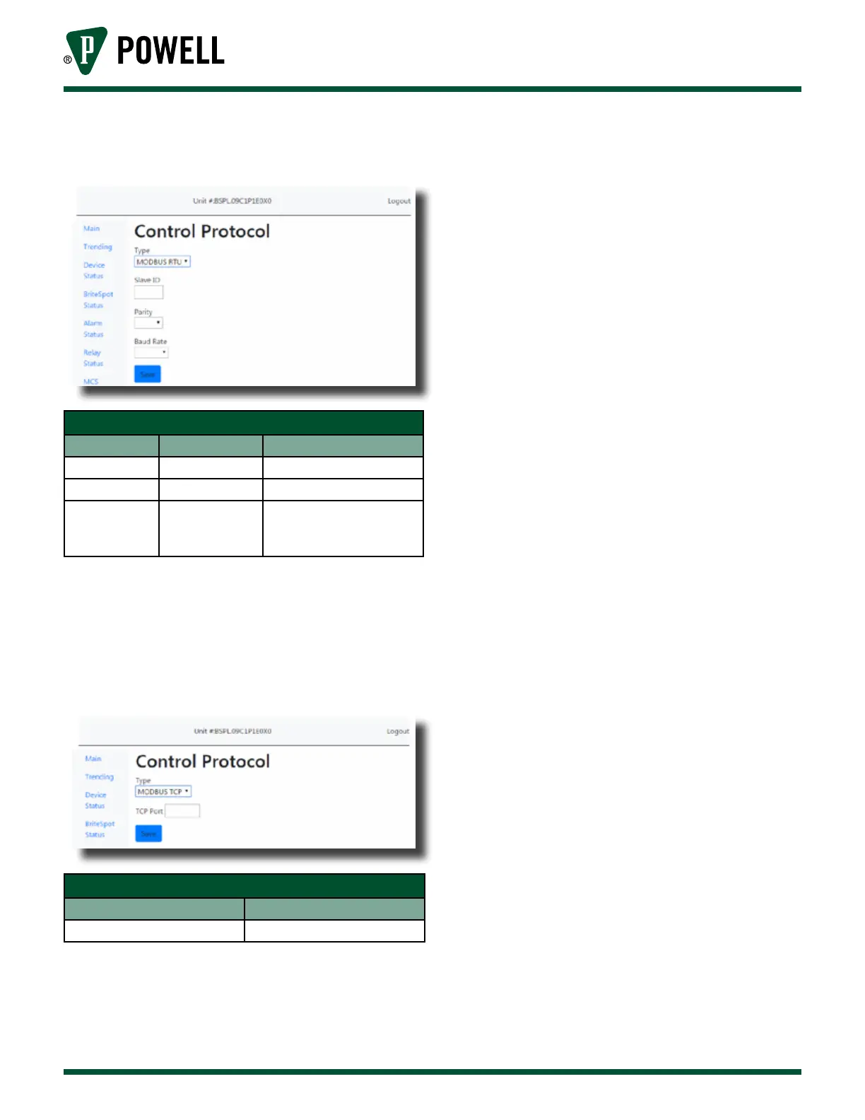
Figure 43 Control Protocol Configuration Web
Page - MODBUS RTU
Table I MODBUS RTU Configuration Settings
Parameter Default Value Range/Options
Client ID 1 1-247
Parity Even Even, odd, none
Baud Rate 19200
300, 1200, 2400, 4800,
9600, 19200, 38400,
57600, 115200 Baud
Note: The RS-485 interface only allows 31
devices on a given bus without the use
of repeaters.
Figure 44 Control Protocol Configuration Web
Page - MODBUS TCP
Table J MODBUS TCP Configuration Settings
Parameter Range/Options
MODBUS PORT 1=65535
v. Alarm Configuration
The BriteSpot® Plus has eight user
configurable alarms. Two alarm
types are available, absolute
temperature and absolute current,
which trigger a warning and/
or alarm when the measured
temperature or current respectively
exceed the user configured limits.
These must be first setup from the
web interface, however, once this
has been done the majority of their
settings can also be configured via
the user interface.
To access the alarm configuration
pages (Figure 45), click on “Alarm
Status” in the navigation bar, then
click on the number of the alarm
to be configured i.e. “1”, then click
“Configure Alarm”. They can also
be accessed by clicking on the
associated alarm status indicator
on the home page, followed by
“Configure Alarm”.