Powered by Safety
®
51
Appendix C
01.4IB.48041
Appendix C Power Cards (PWR1)
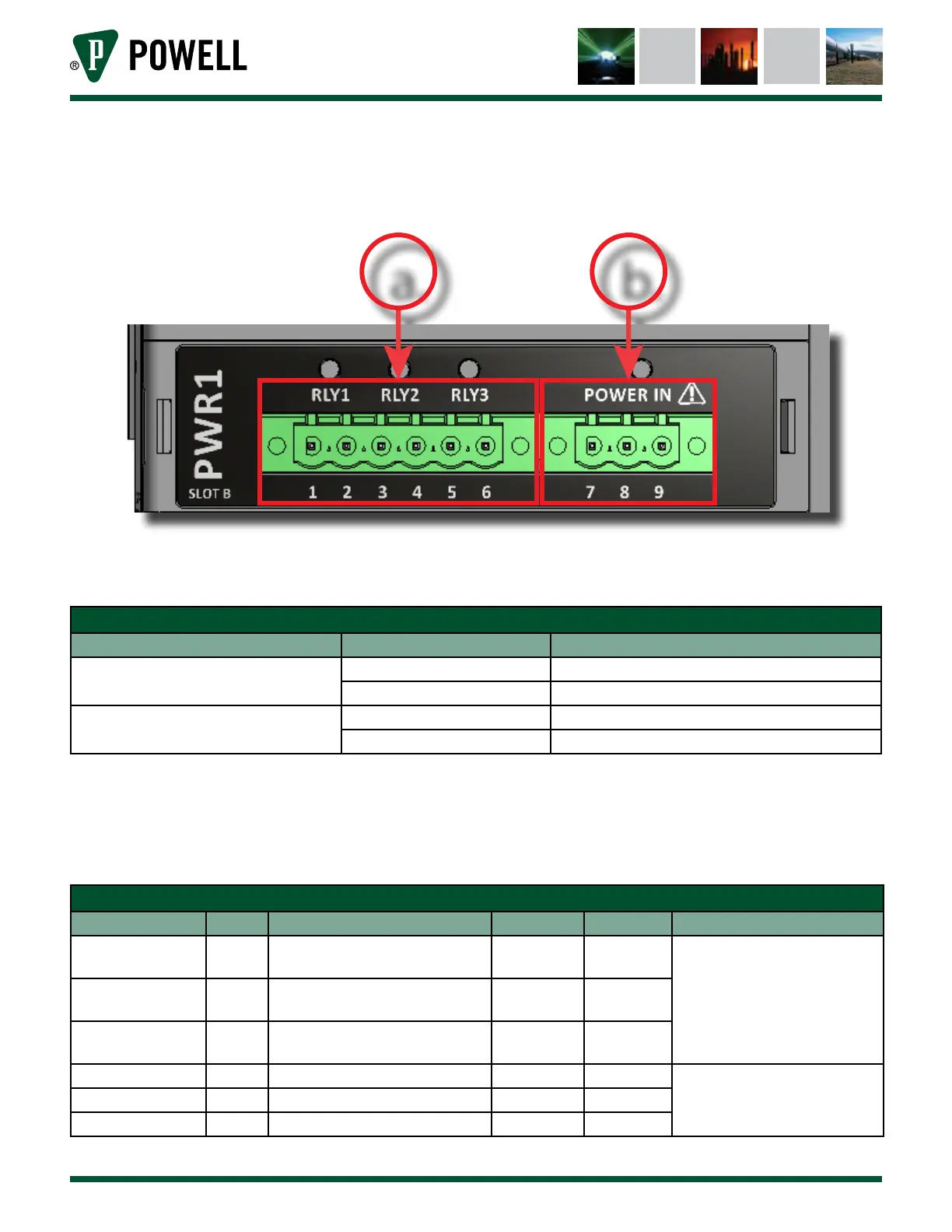
Figure 68 PWR Card 1
a. b.
Figure 68 shows PWR Card 1 and highlights the various ports and indicators. There are four indicator
LEDs on PWR 1. The meaning of the indicator LEDs is explained below.
Table Z PWR 1 Indicator LEDs
Indicator LED Color Meaning
RLY1, RLY2, RLY3
Green Corresponding Relay Closed
O Corresponding Relay Open
Power
Green 12V Power is Being Supplied
O No Power is Being Supplied
PWR 1 has two interface ports with the following applications.
a. Terminals 1-6: Relay Output
b. Terminal 7-9: Input Power
Table AA PWR 1 Wiring Recommendations
Terminal Number Name Function Wire Gauge Wire Type Replacement Connector
1-2 RLY1
Relay 1 dry contacts
(normally open)
22 SIS(VW-1)
Phoenix Contact part:
1805343
3-4 RLY2
Relay 2 dry contacts
(normally open)
22 SIS(VW-1)
5-6 RLY3
Relay 3 dry contacts
(normally open)
22 SIS(VW-1)
7 L (+) Line or positive input power 14 SIS(VW-1)
Phoenix Contact part:
1805314
8 N (-) Neutral or negative input power 14 SIS(VW-1)
9 GND Ground Connection 14 SIS(VW-1)