Powered by Safety
®
32
Usage
01.4IB.48041
BriteSpot® Plus
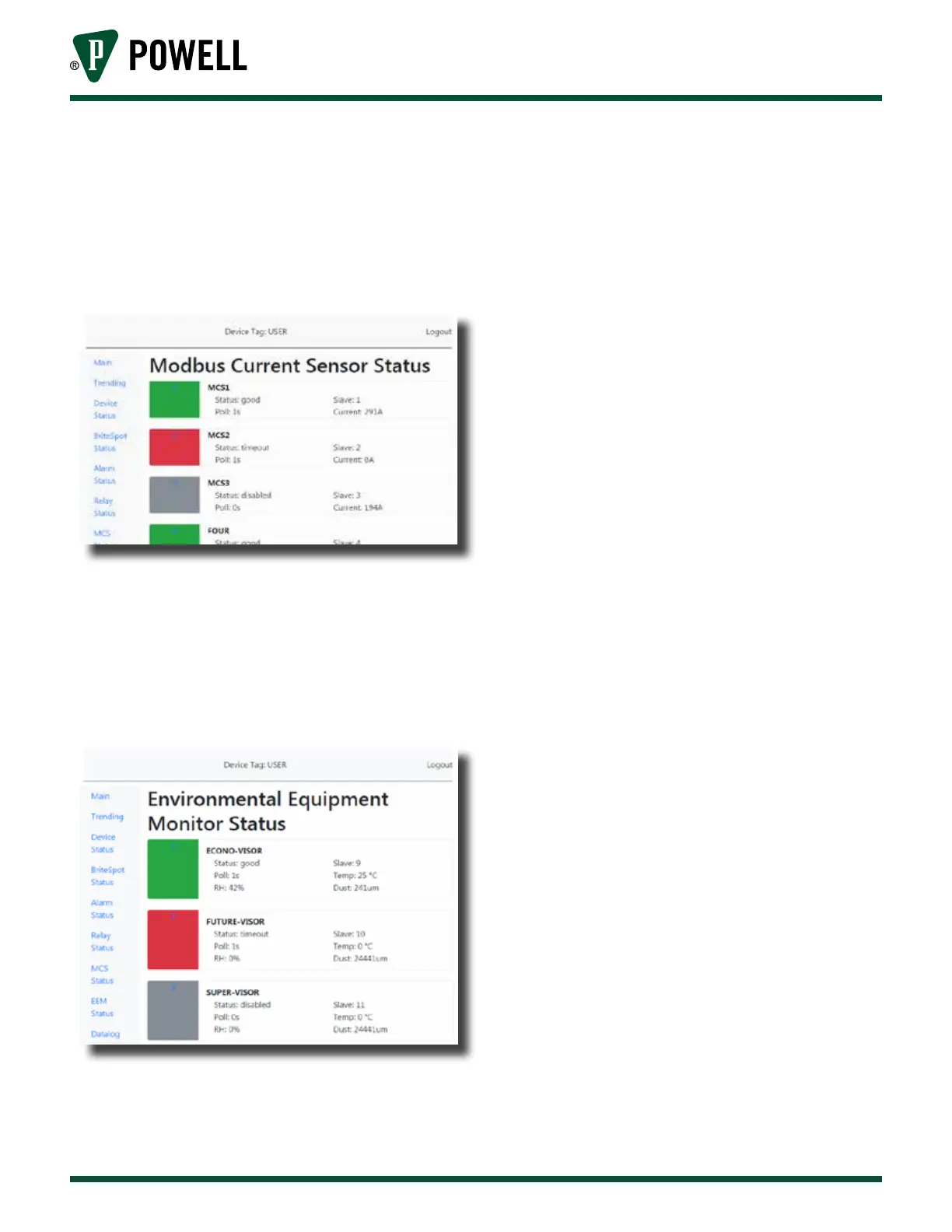
vi. The MCS status page (Figure 38)
allows the user to view the
communication status, slave ID,
polling rate, and measured current
of each connected MCS device.
Figure 38 MCS Status Page
vii. The EcoVisor™ status page
(Figure 39) allows the user to view
the communication status, slave ID,
polling rate, and measured values of
each connected EcoVisor device.
Figure 39 EcoVisor™ Status Page
B. confiGurAtion
1) Web Interface
a. Connecting to the Device
i. Connect a CAT5 Ethernet cable
directly between the Ethernet ports
on the computer and BriteSpot® Plus
to be configured.
ii. Ensure the power is connected to
the device and link is established.
iii. Type in the IP address in the browser
(default: 192.168.1.51; for details on
how to view the current IP see
Table F Menu Navigation)
iv. From the homepage the user can
navigate through the rest of the site
by clicking on the menu options of
the navigation bar on the left.
Note: If connecting via Ethernet directly
to a computer, the Internet Protocol
Version 4 IP address must be set in the
network settings on the computer. For
guidance see Appendix E.
b. Configuration Pages
i. Credential Validation
The changing of any parameters will
require a username and password.
The default values are:
Username: admin
Password: admin
To log in, navigate to the login page
(Figure 40) by clicking “login” at the
top right of the page.