Powered by Safety
®
41
Usage
01.4IB.48041
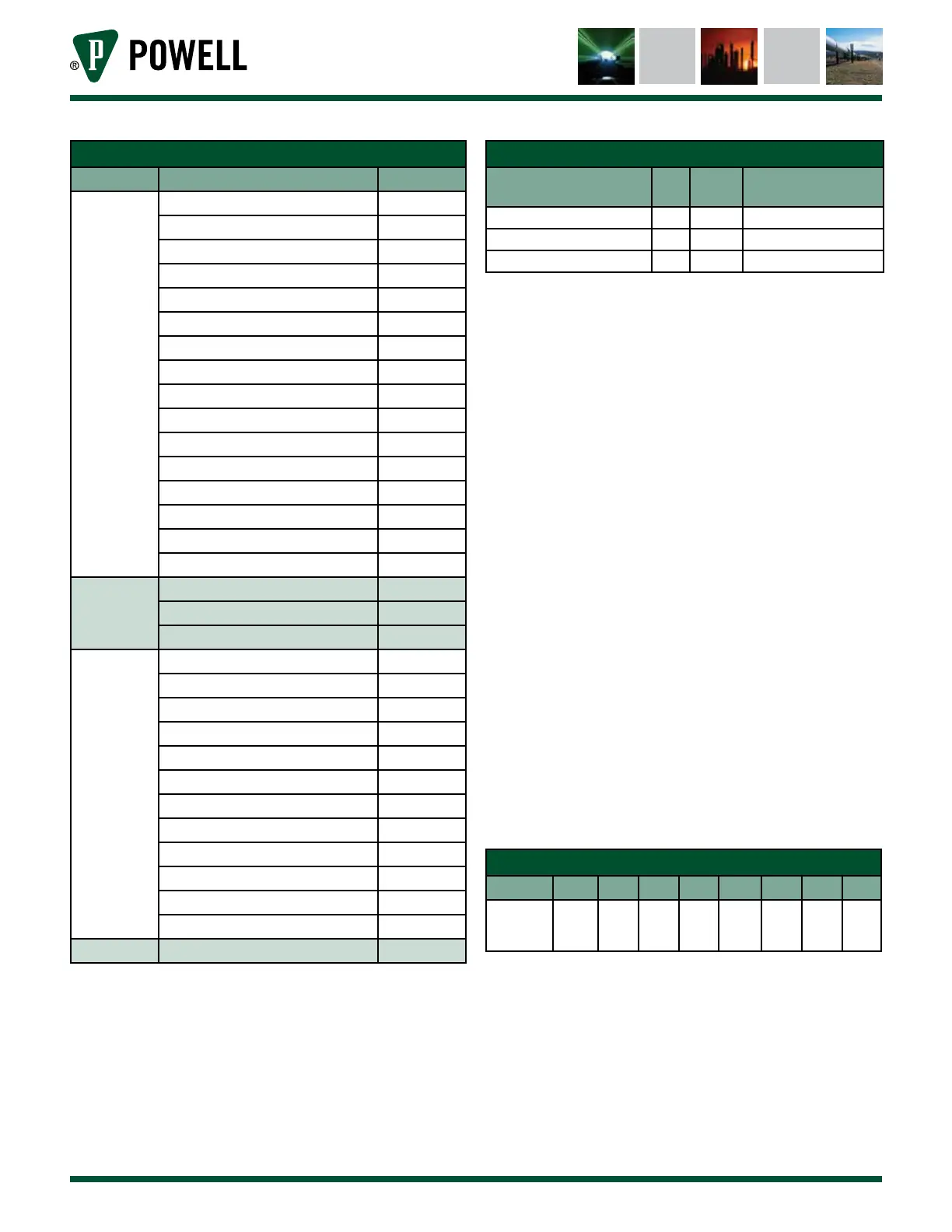
Table T Alarm Source Bit-Mask
Register Source Bit
Low
Register
BriteSpot Plus Channel 1 0
BriteSpot Plus Channel 2 1
BriteSpot Plus Channel 3 2
BriteSpot Plus Channel 4 3
BriteSpot Plus Channel 5 4
BriteSpot Plus Channel 6 5
BriteSpot Plus Channel 7 6
BriteSpot Plus Channel 8 7
BriteSpot Plus Channel 9 8
BriteSpot Plus Channel 10 9
BriteSpot Plus Channel 11 10
BriteSpot Plus Channel 12 11
BriteSpot Plus Channel 13 12
BriteSpot Plus Channel 14 13
BriteSpot Plus Channel 15 14
BriteSpot Plus Channel 16 15
Mid 1
Register
BriteSpot Plus Channel 17 16
BriteSpot Plus Channel 18 17
Reserved for Future Use 18 - 35
Mid 2
Register
MCS 1 36
MCS 2 37
MCS 3 38
MCS 4 39
MCS 5 40
MCS 6 41
MCS 7 42
MCS 8 43
EcoVisor 1 44
EcoVisor 2 45
EcoVisor 3 46
EcoVisor 4 47
Hi Register Reserved for Future Use 48 - 63
Example:
Reading Input Registers 30114 - 30116
(Alarm Channel Low - Mid 2 for Alarm 1)
Table U Example Alarm Data
Input Register Address
(Name)
Dec Hex Binary
30114 (Alarm Channel Low) 64 0x 0040 0b 0000 0000 0100 0000
30115 (Alarm Channel Mid 1) 1 0x 0001 0b 0000 0000 0000 0001
30116 (Alarm Channel Mid 2) 0 0x 0000 0b 0000 0000 0000 0000
In the case above, the bits that are set
indicate that BriteSpot® channels 7 and
17 have exceeded the alarm threshold.
b. Relay Output
The BriteSpot Plus conversion module
is equipped with normally open dry-
contact type relays depending on the
unit configuration (Appendix C). The
relay are intended to be used by the
operator for wiring to an annunciator
or any similar device should action
be desired upon the occurrence of an
alarm. The specific settings for the
relays may be configured through the
UI or the web page.
There are four relay status registers
which are described in Appendix D.
The first indicates whether each relay
triggers on a warning or alarm. The
other three indicate what alarms trigger
the given relay.
Table V Relay Input Bit Mask
8-15 7 6 5 4 3 2 1 0
Reserved
for Future
Use
Alarm
8
Alarm
7
Alarm
6
Alarm
5
Alarm
4
Alarm
3
Alarm
2
Alarm
1
Example:
Reading Input Registers 30051 (Relay 1
Inputs)