Powered by Safety
®
31
Usage
01.4IB.48041
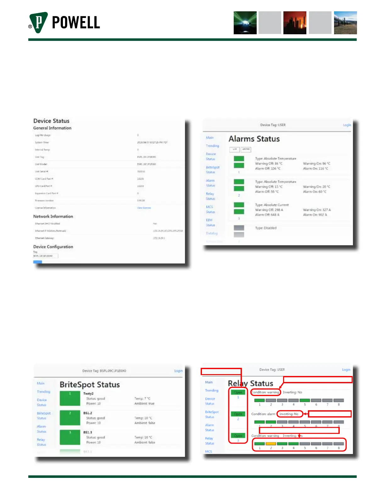
ii. The device status page displays
general information about the
BriteSpot® Plus. The device tag can
be edited on this page (Figure 34).
Figure 34 Device Status Web Page
iii. The BriteSpot status page
(Figure 35) displays the current
status and temperature of the
channel as well as the optical
power and whether the channel is
measuring ambient temperature or
not.
Figure 35 BriteSpot® Status Page
iv. The alarm status page (Figure 36)
displays the current and latched
state of all the alarms as well as the
type and setpoints.
Figure 36 Alarm Status Page
v. The relay status page (Figure 37)
displays the current state of the
three output relays. It also shows
which alarm sources contribute to
the actuation of a given relay and
their states (good/warning/alarm).
A grayed out box indicates that the
given alarm is not linked to that
relay.
Figure 37 Relay Status Page
Alarm condition that wil cause relay to actuate
Is the relay’s action inverted?
Current state of relays 1 - 3
Indicates which alarms actuate the relay and their states