Powered by Safety
®
29
Usage
01.4IB.48041
2) Web Interface
Once connected to the BriteSpot® Plus
via the web interface (see Ch 5 Usage,
B. Configuration), a host of information
and configuration options are presented.
The following section provides a general
overview of the pages displayed. More
detailed descriptions and specifics on
establishing the connection are provided in
the remaining sections of this chapter.
The general format of the web interface is
that of a Navigation Bar in the left portion
of the page and data fields on the right
(Figure 29). Clicking on any of the menu
options in the Navigation Bar will update
the page and display the corresponding
content.
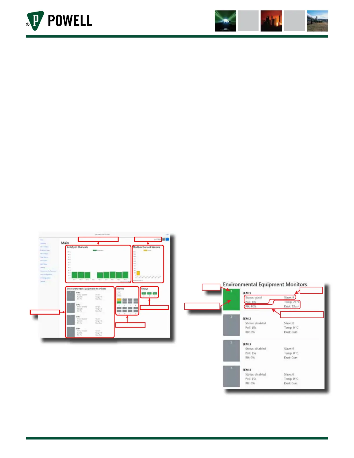
Figure 29 Web Interface Navigation
Live BriteSpot Temperatures Live MCS Currents
EcoVisor Display Area
Alarms Display Area
Relays Display Area
a. Main Pages
The main page consists of five display
areas:
• Live BriteSpot channel temperatures
• Live Modbus Current Sensor units
• EcoVisor™ environmental monitor
• Alarms
• Relays
Both the BriteSpot and the MCS live
display areas simply display the present
values being measured by these
sensors, and will reflect any alarm states
being triggered by a specific sensor,
displaying:
• Green = good
• Amber = warning
• Red = alarm
The remaining three areas of the
main page are more complex, and are
described below.
i. The EcoVisor area displays the
present state of any alarms using a
given EcoVisor as a source, as well
as the values of measured humidity,
temperature dust and information
about communications with the
unit (Figure 30). The EcoVisor status
pages can be directly accessed by
clicking on the EcoVisor ID number
in the status display.
Figure 30 EcoVisor™ Main Page Display
EEM ID
Status Indicator
COM Info
Current Sensor Data