DESCRIPTION OF PROGRAMMING PARAMETERS
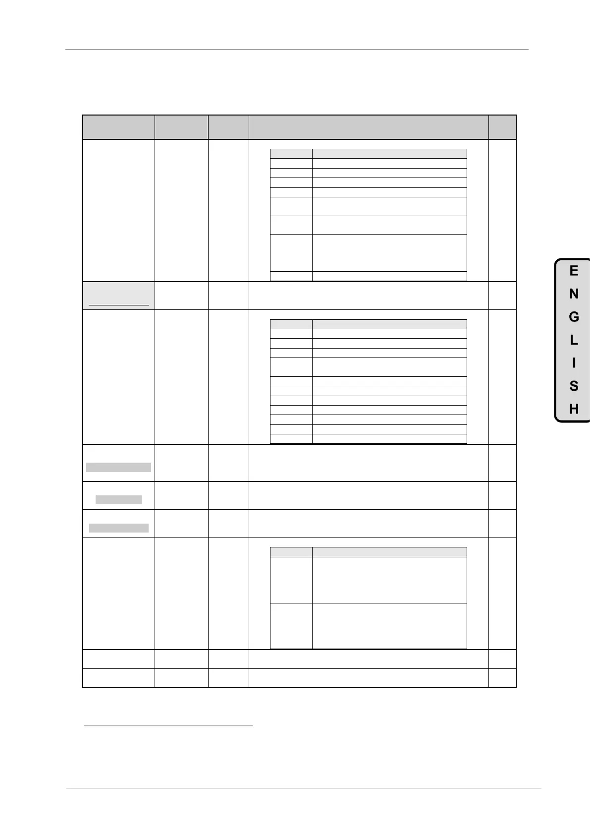
4.6. Group 6 – G6: PID Control
Parameter /
Default Value
G6.1 / Source
selection for
introducing
reference signal
NONE
AI1
AI2
RESERV
MREF
LOCAL
LocPID
COMMS
It allows user to select the reference source for the setpoint of the PID regulator.
PID setpoint introduced by Analogue Input 1.
PID setpoint introduced by Analogue Input 2.
PID setpoint introduced by Digital Inputs
configured as Multi-references.
PID setpoint introduced by keypad. Value can be
adjusted in screen 'G3.3 LOCAL SPD'.
PID setpoint introduced by keypad. Value is set in
'G6.2 PID LOC'. It allows user to have two speed
references because 'G3.3 LOCAL SPD' is not
modified.
PID setpoint introduced by communications
2 PID LOC=+100.0%
[5]
PID LOCAL SETPOI
G6.2 / PID local
reference
When ‘locPID’ is set as setpoint source, the reference introduced by keypad will
be memorized in this parameter. The value of the parameter 'G3.3 LOCAL SPD' is
not modified and it is available if we want to use alternative speed reference.
G6.3 / Selection
of feedback
signal source
NONE
AI1
AI2
AI1+AI2
COMMS
MtrTrq
AbsMTq
Mtr I.
MtrPwr
BUSVdc
PhiCos
To select the source of the feedback signal for the PID control loop.
The PID function is not active
Feedback signal through the Analogue Input 1
Feedback signal through the Analogue Input 2
Feedback will be the addition of the signals
introduced through the Analogue Inputs 1 and 2
Feedback signal through communications
4 GAIN Kp=8.0
PID PROPORTIONAL
G6.4 /
Proportional gain
of PID control
It allows setting the proportional gain value of the PID regulator. If you need a
higher control response, increase this value.
Note: If this value is increased too much, a higher instability in the system can be
introduced.
5 INTEGRAL = 0.1s
PID INTEGRAL
G6.5 / Integration
time of PID
control
It allows setting the integration time of the PID regulator. If you need a higher
accuracy you should increase this value.
Note: If this value is increased too much, the system can become slower.
6 DIFFEREN = 0.0s
PID DIFFERENTIAL
G6.6 / Derivation
time of PID
control
It allows setting the derivate time of the PID regulator. If you need a higher
response, you can increase this value.
Note: If this value is increased too much, accuracy can decrease.
G6.7 / PID output
inversion
It allows inverting the PID output of the drive.
PID regulator responds in normal mode, that
means, when the feedback value is above the
reference signal value, speed will be decreased.
If the feedback value is below the reference
signal value, speed will be increased.
PID regulator responds in inverse mode. So,
when the feedback value is above the reference
signal value, speed will be increased. If the
feedback value is below the reference signal
value, speed will be decreased.
It allows setting the value of a low pass filter. It will be used to soften the feedback
in the PID.
It shows the difference between the reference 'G6.1 SEL REF' and the feedback
signal of the process 'G6.3 SEL FBK'.
Note: PID functions will be set here if this function is enabled in the parameters 'G3.1 REF1 SPD=LOCAL' or 'G3.2 2
REF2 SPD=LOCAL'.
[5]
It will be available if 'G6.1 SEL REF = locPID'.