FAULT MESSAGES. DESCRIPTIONS AND ACTIONS
6. FAULT MESSAGES. DESCRIPTIONS AND
ACTIONS
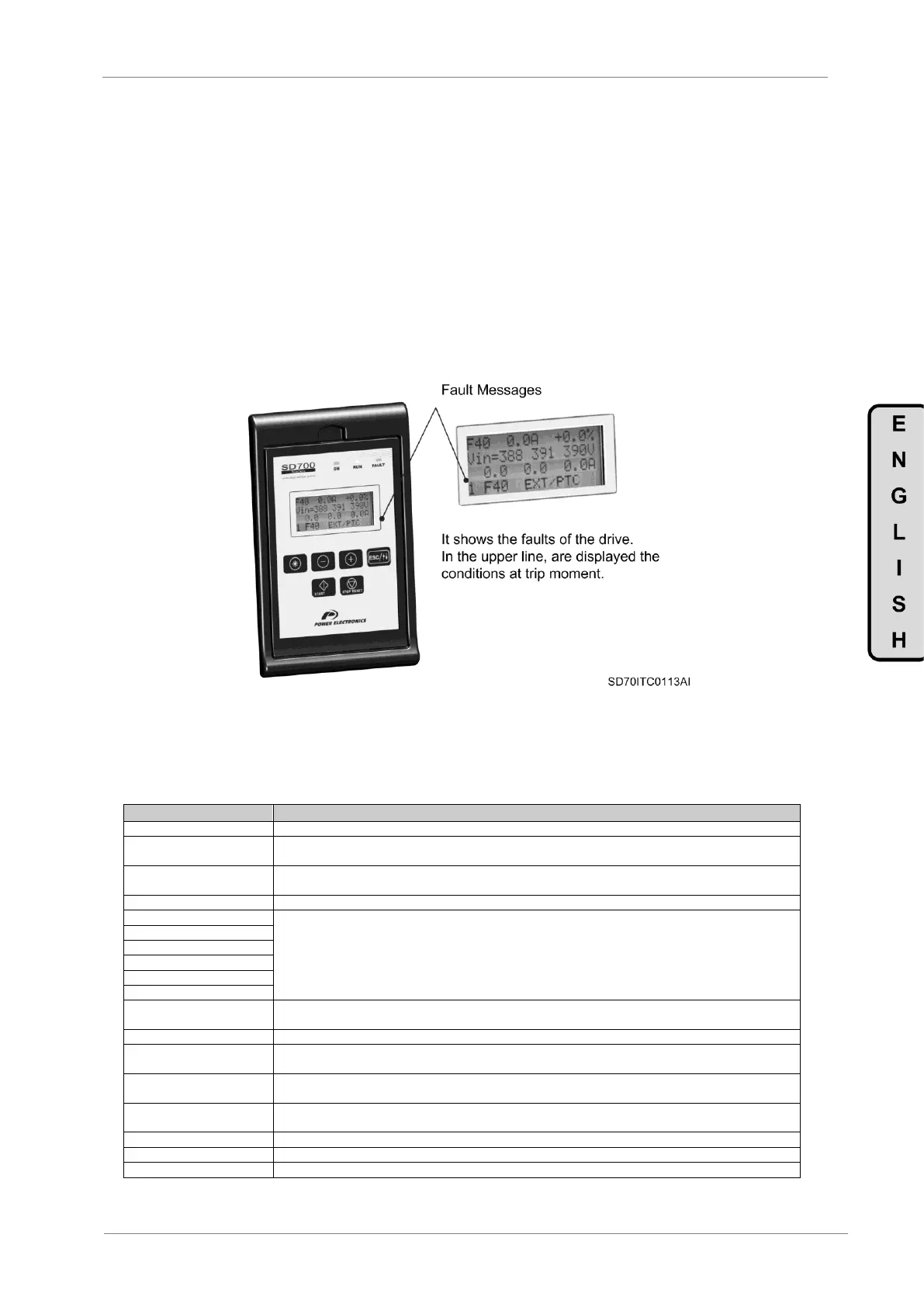
When a fault occurs the SD700 will stop the motor and show the generated fault on the display. You can
display this fault in the programming line (lower line) while motor current and the speed values at the
moment of the fault are displayed in the upper line.
It is possible to navigate through the additional display lines to access other status parameters without
resetting the fault. These additional status parameters offer further information about the moment at which
the fault occurred. Additionally, the FAULT led will blink and the fault message will be displayed until the
fault is remedied and the drive is reset.
Figure 6.1 Fault displaying – Programming Line
6.1. Description of Fault List
Drive is operative. There is no fault.
Output current has reached a dangerous level. Its value is above 220% of the drive rated current. Protection is
activated instantaneously.
DC Bus voltage has reached a dangerous level >850VDC. Hardware Protection. Drive will turn off the output to
the motor.
DC Bus voltage and the output current of the equipment have reached dangerous levels.
Internal protection within the appropriate IGBT semiconductor has acted.
Automatic internal protection of several of the IGBT semiconductors has acted or safe stop contact of the drive
(connected to an external circuit by the user) has been activated (for example, emergency stop).
Power supply loss of any input phase for a time higher than 20ms has occurred.
Input voltage imbalance greater than ±10% of average input power supply of SD700 for a time higher than
100ms.
Average supply voltage has exceeded the value set in ‘G11.6 HIGH VOLT’ for greater than the time set in ‘G11.7
HIGH V TO’.
Average supply voltage is lower than the value set in ‘G11.4 LOW VOLT’ for greater than the time set in ‘G11.5
LOW V TO’.
Unstable bus voltage. There is a DC Bus voltage ripple higher than 100VDC for more than 1.1sec.
DC Bus voltage has exceeded critical operating level (>850VDC). Software Protection.
DC Bus voltage is lower than critical operating level (<350VDC).