VISUALIZATION AND STATUS PARAMETERS. GROUP G0
3.4. Parameters SV.4 – Internal Visualisation
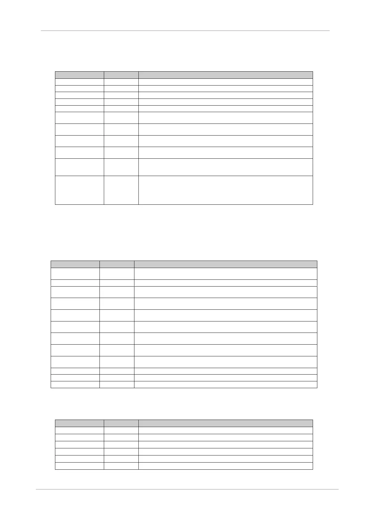
It shows the present code fault. See fault history G13.
It shows the drive rated current (maximum current of the equipment at 50ºC).
It shows the drive rated voltage.
It shows the software version installed into the equipment.
It shows the hardware version of the equipment.
It shows the reference value in PID mode of the equipment standard program.
It shows the feedback value in PID mode of the equipment standard program.
It shows the error value in PID mode that means, the difference between the reference value
and the real value of the system feedback signal.
It shows if comparators are activated or not.
X: Active / 0: Not Active.
It shows if the equipment is in faulty status.
If the equipment is in faulty status, it shows the status of the drive before the fault is
produced; when there is not fault, it shows ‘NO FLT’.
When it is set to ‘Y’ (YES), the parameters of groups ‘SV.1 Motor Visualization’ and ‘SV.2
Drive Visualization’ are hold with the last values at the moment of the last fault is produced.
If the user sets the parameter to ‘N’ (NO), or after 135 seconds are elapsed, the parameters
will show the actual values again. The hold values are saved in memory until next fault will be
produced, even if the input power of the drive is lost.
3.5. Parameters SV.5 – Programmable Parameters
This group is not only a display group. Some parameters such as speed, pressure and inch speeds
can be adjusted in this group. These parameters are also available in their corresponding parameter
groups. This is a simple way to allow user adjustment of basic parameters without entering the main
programming groups.
It shows the speed reference value in local mode (introduced by keypad). See G3.3 parameter for
additional data.
It allows user to select the PID reference in local mode. See G6.2 parameter for additional data.
It allows user to set the speed value assigned to Multi-reference 1. See G14.1 parameter for
additional data.
It allows user to set the speed value assigned to Multi-reference 2. See G14.2 parameter for
additional data.
It allows user to set the speed value assigned to Multi-reference 3. See G14.3 parameter for
additional data.
It allows user to set the speed value assigned to Multi-reference 4. See G14.4 parameter for
additional data.
It allows user to set the speed value assigned to Multi-reference 5. See G14.5 parameter for
additional data.
It allows user to set the speed value assigned to Multi-reference 6. See G14.6 parameter for
additional data.
It allows user to set the speed value assigned to Multi-reference 7. See G14.7 parameter for
additional data.
It allows user to set the step frequency 1 value. See G15.1 for additional data.
It allows user to set the step frequency 2 value. See G15.2 for additional data.
It allows user to set the step frequency 3 value. See G15.1 and 2 for additional data.
3.6. Parameters SV.6 – Registers
This group includes several registers of general information about the drive use. Therefore, we can
visualize a total and partial counter for running time (RUN).
It shows the total time during which the drive is running (RUN).
It shows the partial time during which the drive is running (RUN).
It allows resetting the counter of partial time for running status (RUN).
Shows the drive total energy consumption.
Shows the drive partial energy consumption.
The user is able to reset the partial energy counter.