DESCRIPTION OF PROGRAMMING PARAMETERS
4.19.3. Subgroup 19.3 – S19.3: Motor Model
Parameter /
Default Value
1 R. STR=1%
STATOR RESISTOR
G19.3.1 / Stator
resistance (Rs)
Set as a percentage of motor rated impedance.
Stator resistance (Rs): It is used to compensate the iron losses and copper losses
of the motor.
Rotor resistance (Rr): A key parameter that directly concerns the output torque.
Motor inductance (Lm): It is an interesting parameter if the equipment works with
vector control and G19.1.2 = AVC. It is the main inductance of the motor that
defines the magnetic field strength. It is a key parameter that directly concerns the
motor flux. Typical values can range from 75% (small motors) to 800% (large
motors).
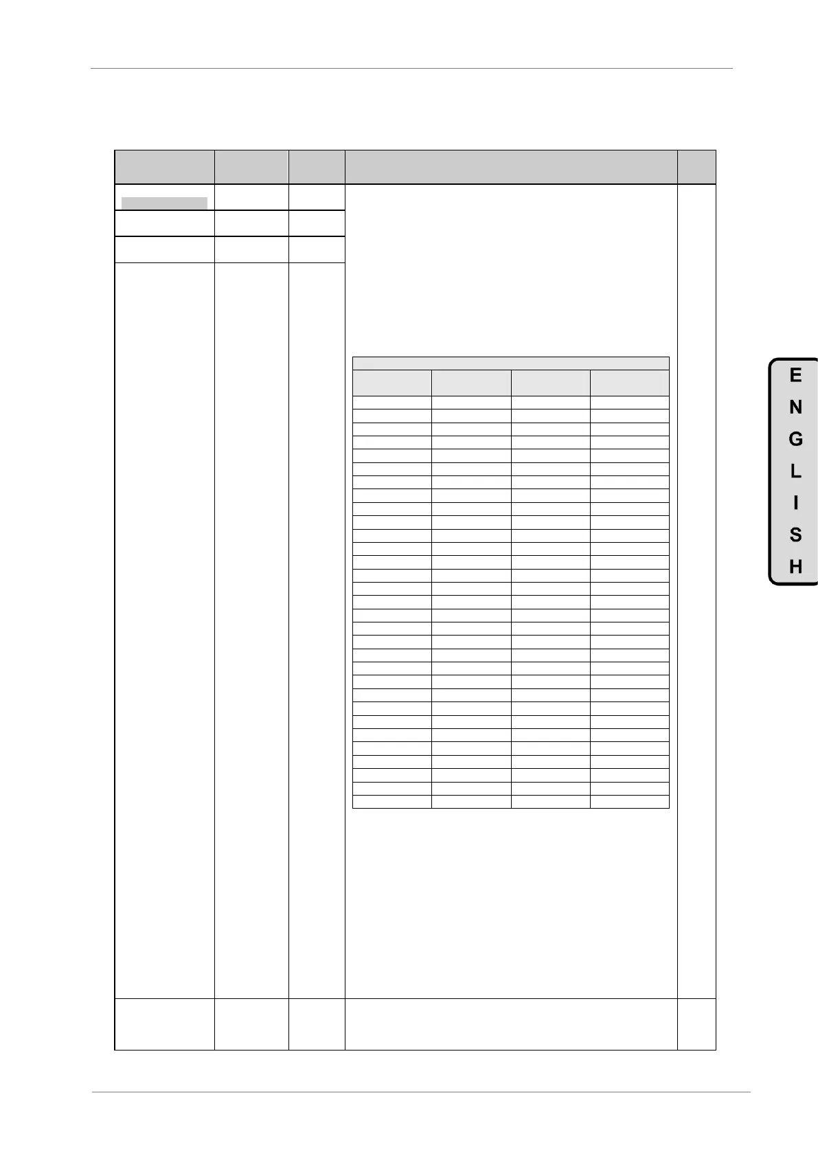
Note: The following table shows the default values for drives of any nominal
voltage.
Default Values for All Powers
G19.3.4 = 5% of G19.3.3
Adjust mode: When initializing factory settings (1) or manually modifying the
Motor Nominal Power (G2.3) (2), the values are initialized according to the table,
values outside the table are estimated according to the table.
When auto-tuning is performed (G19.1.8) (3) the value of parameters is
automatically changed to the value measured.
In all cases, the adjustment range is + / -30% of initialized value in any of the
three scenarios given (1), (2), (3).
Note: If this G19.3.1 is set too high then increased motor currents can reach the
current limit preventing further acceleration to the motor. We recommend
consulting the above standard value table as Rs value is variable according to the
drive capacity.
G19.3.2 / Rotor
resistance (Rr)
G19.3.3 /Motor
inductance (Lm)
G19.3.4 / Stray
inductance
The weakening field occurs when the drive cannot give more voltage than it
receives from the power supply, and when the frequency exceeds the rated
frequency of the motor. In this event, only the frequency will be regulated and the
voltage will keep constant producing the weakening of the motor field.