DESCRIPTION OF PROGRAMMING PARAMETERS
4.19. Group 19 – G19: Fine Tuning
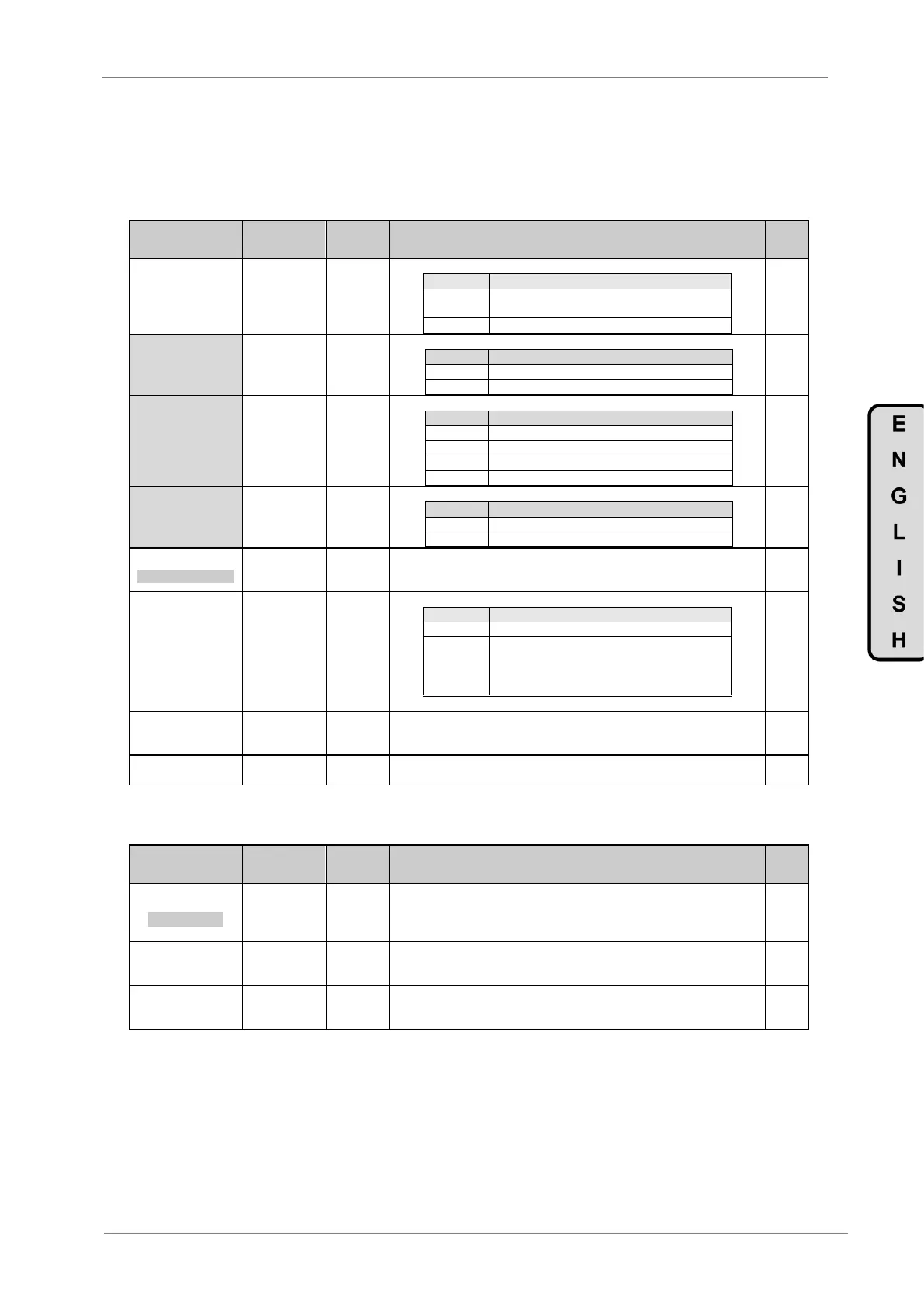
4.19.1. Subgroup 19.1 – S19.1: IGBT Control
Parameter /
Default Value
G19.1.1 /
Selection of
control type
This selection defines the drive control type.
Scalar control mode. Drive carries out the control
applying a voltage / frequency ramp to the motor.
2 VECTOR CTR =
PMC
(*) Available if G19.1.1 =
VECT
G19.1.2 / Vector
Control mode
Set the vector control mode:
3 PMC = OL SP
(*) Available if G19.1.1 =
VECT and G19.1.2 = PMC
G19.1.3 / Power
Motor Control
mode
Set the Power Motor Control mode:
Open Loop Torque Control.
Close Loop Speed Control.
Close Loop Torque Control.
4 AVC = CL SP
(*) Available if G19.1.1 =
VECT and G19.1.2 = AVC
G19.1.4 /
AdvanceVector
Control mode
Set the Advance Vector Control mode:
Close Loop Speed Control.
Close Loop Torque Control.
5 FREQ=4000Hz
MODULAT FREQUENC
G19.1.5 /
Commutation
frequency
It allows modification of the drive switching frequency. This function can be used
to reduce audible motor noise.
This control mode improves motor noise tone.
Pewave control deactivated.
Pewave control activated.
Commutation frequency (G19.1.2) is slightly
modified on a random basis to improve the noise
tone generated by the motor.
G19.1.8 / Motor
parameter auto-
tuning
This selection allows executing a motor auto-tuning, in order to get the stator
resistance value of the motor. This value will be saved in parameter G19.3.1.
G.19.1.9 /
Over-modulation
With this option, it allows supplying more motor voltage at 50Hz.
4.19.2. Subgroup 19.2 – S19.2: Motor Load
Parameter /
Default Value
1 MIN FLUX = 100%
MINIMUM FLUX
Allows setting of the minimum flux level used by the motor during low load
conditions. With this dynamic system of flux optimization, noise and power losses
are reduced. Adaptation of the flux level during low load conditions occurs
automatically. The algorithm will be disabled when this parameter is set to 100%.
G19.2.3 / Initial
voltage
Sets an initial voltage value applied to the motor during the starting. Using this
function it is possible to improve breakaway torque when starting heavy loads.
Note: Set a low value first. Increase the value gradually until the load starts easily.
G19.2.4 / Slip
compensation
If this function is active, it helps to compensate the slip on the motor. In case of
heavy load able of provoking a high slip during the starting, set this parameter to
YES.