DESCRIPTION OF PROGRAMMING PARAMETERS
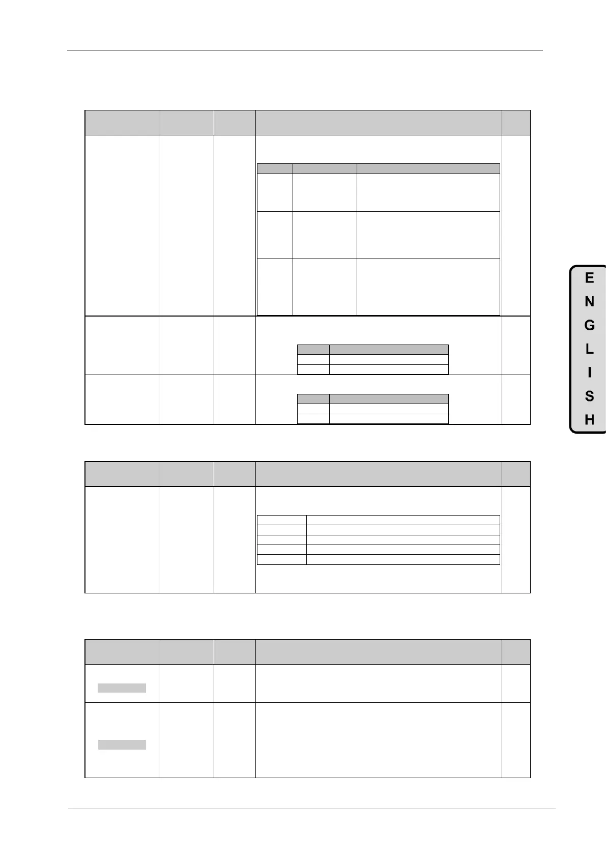
4.4.5.2. Subgroup S4.6.3 – Input O.F
Parameter /
Default Value
This parameter receives both the Start order and the Run status coming from the
master. This status will be sent to the subgroups G4.1.1 and G4.1.2, allowing the
slave to start with Start order or the Run status of the master.
The equipment will not take into account the
START order or the RUN status. If we select
FIBER in G4.1.1 or G4.1.2, the variable
speed drive will not start.
The Start order of the master will be sent to
the FIBER option in the groups G4.1.1 and
G4.1.2. It means that if we select the fiber
option in the control mode while the master
has a Start order, the slave will start.
The RUN status of the master will be sent to
the FIBER option in G4.1.1 and G4.1.2.
When the fiber option is selected in a control
mode and the master is in RUN, the slave
will start and won’t stop till the RUN has
been disappeared of the master.
G4.6.3.6 /
Control (Master)
When this option is selected in the master drive and the system is working in
closed ring mode, the master will STOP and show “F76 SLAVE O.F”, if one or
more slaves are faulted. Otherwise, the master will continue running.
G4.6.3.7 / SPIN
STOP (Slave)
If we select this option, when the master will fault for any reason, all the slaves will
stop automatically through a spin stop.
4.4.5.3. Subgroup S4.6.5 – T/O F.O
Parameter /
Default Value
G4.6.5/ Time out
optical fiber
(Slave)
Permits Open loop and close loop mode selection. Additionally for close loop
mode, enable to establish the timeout response for slave. If the master does not
receive response within the time selected the slave sets “F77 OPT FIB TO” fault.
Otherwise, and also in the open loop, the option of “listener” slave is available.
The slave only pays attention on the bus communications and does not make any
action. This mode has been created to work with CANOpen and Devicenet boards
4.5. Group 5 – G5: Acceleration and Deceleration Ramps
Parameter /
Default Value
1 ACC1=5.0%/s
INITIAL ACCEL
G5.1 /
Acceleration
ramp 1
Allows user to set acceleration ramp 1. The setting is in acceleration units
(increase in percentage of speed per second). For example, a 10%/s ramp means
that the drive increases its speed by 10% of motor rated speed for each second.
This ramp will be set according to the requirements of each process.
2 DECEL1=1.0%/s
INITIAL DECEL
G5.2 /
Deceleration
ramp 1
Allows user to set deceleration ramp 1. The setting is in deceleration units
(decrease in percentage of speed per second). For example, a 10%/s ramp
means that the drive decreases its speed by 10% of motor rated speed for each
second. This ramp will be set according to the requirements of each process.
Note: For drives which input voltage is 400V, the default values will be:
- From 6A to 48A =10%/sec
- From 60A to 170A =5%/sec
- From 210A to Imax =2%/sec