5.1.1.1. Operation Example of Modbus Function Code Nº 3 (Registers Reading)
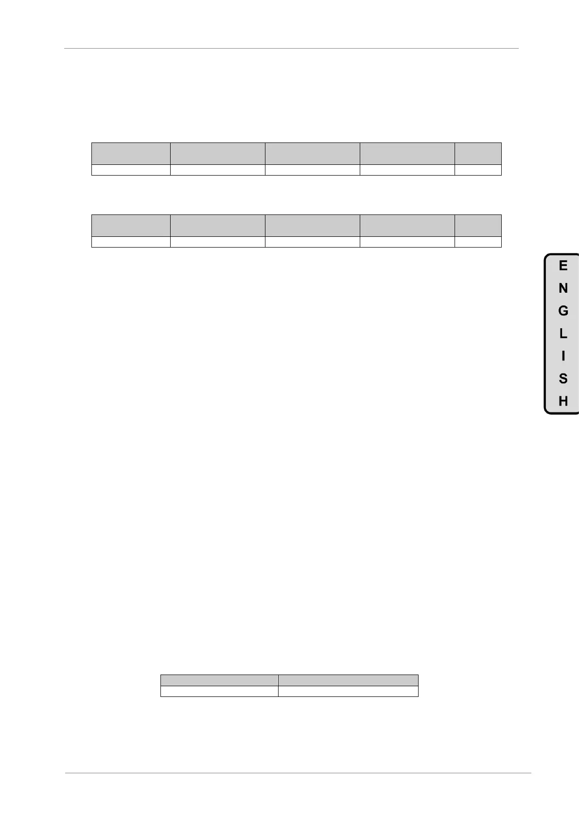
We suppose that we want to read the motor current (nameplate data) via communications. This
data corresponds to the parameter G2.1 ‘1 MTR CUR=00.00A’. The frame that should be
transmitted is:
We suppose that instantaneous current of the equipment is 8,2 A. (Modbus value 82 decimal =
0x52 Hexadecimal). The answer of the slave will be:
5.1.2. Modbus Function Code Nº 16: Registers Writing
This function code allows the Modbus controller (master) to write the content of the data registers
indicated in the drive (slave), whenever those registers are not of Read only. Registers writing by
the master does not impede the later modification of those registers by the slave.
The implementation of this function code in the drive allows writing up to 5 registers of the drive in
a single frame.
Next, a frame is shown where the master tries to write the content of 1 register that stores the
acceleration time. The information that should be attached in the ask frame is the following one:
Data address of the slave.
Modbus function code (16 Registers writing).
Starting Data Address.
Registers number for writing.
Bytes number for writing.
Content of registers for writing.
CRC-16 code.
The answer of the slaves includes:
Data address of the slave.
Modbus function code (16 Registers writing).
Starting Data Address.
Written registers number.
CRC-16 code.
5.2. Addressing Modes
5.2.1. Broadcast Addressing Mode
Broadcast addressing mode allows the master to access at the same time to all of the slaves
connected to the Modbus network. The Modbus function code that admits this global addressing
mode is:
In order to access to all of the equipments connected in a Modbus network, you must use the
address 0.
When this address is used, all of the slaves in the Modbus network make the required task but
they do not prepare any answer.