DESCRIPTION OF PROGRAMMING PARAMETERS
4.8. Group 8 – G8: Outputs
4.8.1. Subgroup 8.1 – S8.1: Output Relays
Parameter /
Default Value
G8.1.1 /
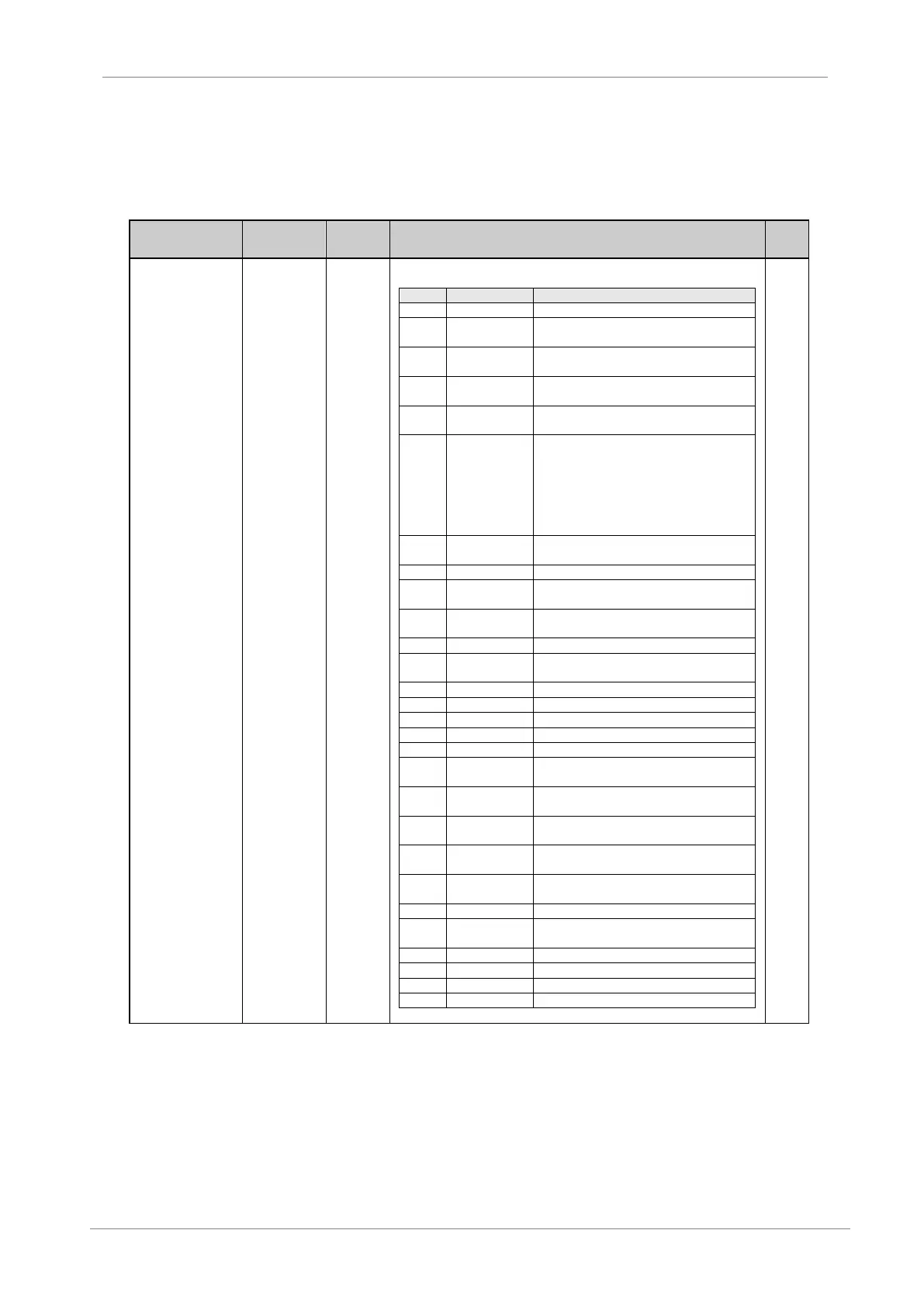
Selection of
Relay 1 control
source
It configures the operation of each output relay according to the options shown in
the following table:
When the drive is powered the output relay is
activated.
There is no fault in the drive. When a fault
occurs, the relay will be activated.
Drive fault or low input voltage will activate
the relay.
Relay is active when the drive has received
the start command.
The relay will be energized after the drive is
started (the speed is increasing).i.e. G8.1.1 =
04 and G8.1.2 = 05. Start command is on,
relay 1 is on and immediately relay 2 is on.
Stop command is activated, then relay 1 is
automatically off BUT relay 2 will be on until
drive was completely stopped.
Drive is ready for start (no fault and no
warning).
Drive is running at zero speed.
Speed has reached the value set as
reference.
The relay is activated when the speed
direction is negative.
The relay is activated when the speed refer.
direction is negative.
Speed limit has been reached.
Motor current limit has been reached.
DC Bus voltage limit has been reached.
Torque limit has been reached.
When the comparator 1 output is active, relay
is activated.
When the comparator 2 is output active, relay
is activated.
When the comparator 3 output is active, relay
is activated.
Relay is activated if the alternative ramps are
used.
Relay is activated if reference 2 has been
selected.
Relay is activated if stop mode 2 is used.
Relay is activated if the alternative speed
limits have been selected.
Relay is activated if DC brake is active.
Note: See following page.