DESCRIPTION OF PROGRAMMING PARAMETERS
4.7. Group 7 – G7: Start / Stop Mode Configuration
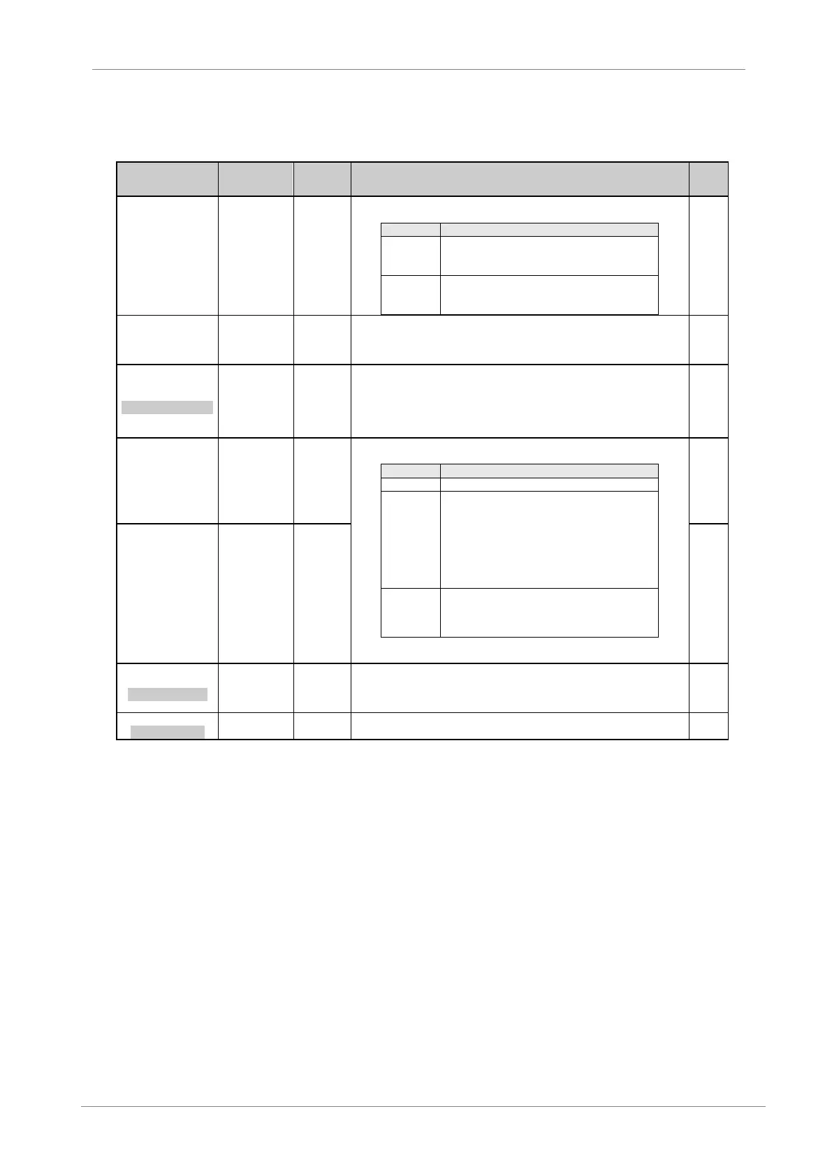
Parameter /
Default Value
It selects the main stop mode of the drive. This value should be configured
appropriately for each application.
The drive will stop applying a frequency ramp to
stop the motor. The rate of stop is determined in
screen 'G5.2 Decel 1'
The drive will turn off the output to the motor. The
motor sill coast to stop. Stopping time is
determined by system inertia.
User can select an alternative stop mode of the drive if required. This value should be
set for each application. For options information see parameter ‘G7.1 STOP 1=RAMP’.
Note: Stop mode 1 or 2 can be selected by digital inputs, by comparator output
functions, or by setting a changing speed for stop mode in 'G7.3 BRK STP 2'.
3 BRK STP 2 = OFF
STP2 UNDER SPEED
G7.3 / Changing
speed for stop
mode
When this parameter is set to a value other than zero a second stopping profile can be
activated based on motor speed. When the drive receives a stop mode 1 command, it
will stop from steady status to the speed set here. At that moment, the drive will apply
stop mode 2 to complete the stop.
Note: Stop mode 1 or 2 can be selected by digital inputs, by comparator output
functions, or by setting a changing speed for stop mode in 'G7.3 BRK STP 2'.
It selects the start mode of the drive. This value should be configured
appropriately for each application.
Drive will start applying a frequency ramp to the motor.
In this mode, the motor shaft speed is automatically
searched for and the frequency output of the drive is
set to match the actual motor speed. From this point
the motor is then accelerated normally up to the
reference speed. This allows starting loads that are still
rotating when the drive receives a start command.
Note: This option is valid when the motor is running at
positive rotation direction.
Operates similar than the option ‘SPIN’. The difference
lies in the possibility of starting loads that are still
rotating independently of the rotation direction of the
motor.
Note: Start mode 2 (alternative start mode) is selected through a digital input
configured with option ’22 START MODE 2’.
6 STAR DLY = OFF
DELAY TO START
Allows setting of a delay time from the moment the drive receives the start command to
the beginning of providing an output frequency to the motor.
Note: After receiving the start command, the drive will wait until the delay time is
elapsed. During this time, the drive status will change to ‘DLY’.
7 STOP DLY = OFF
DELAY TO STOP
Allows setting of a delay time applied from the moment the drive receives the stop
command until the drive stops providing an output frequency to the motor.