COMMONLY USED CONFIGURATIONS
G4: Inputs – S4.1: Digital Inputs.
G4.1.1 / Main Control Mode
2 REMOTE (Drive control is done through control terminals).
G4.1.4 / Digital Inputs configuration
selection
1 ALL PROGRAMMABLE (all digital inputs can be individually
configured by the user).
G4.1.5 / Multi-function Digital Input 1
configuration
05 Start/Stop (Allows the start/stop command to be given by a
switch).
G4.1.6 / Multi-function Digital Input 2
configuration
15 Reference 2 (It allows selecting the alternative speed
reference programmed in G3.2.)
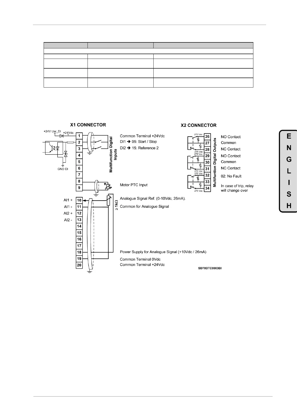
7.2.2. Connections drawing
Terminals 1 and 2: start / stop command (NO status).
Terminals 1 and 3: alternative reference command (NO status).
Figure 7.1 Start / Stop commands by terminals and speed reference by analogue input
Note: Use screened cables for the controls and connect screen to ground.