EasyManuals Logo

Power Electronics SD700 Series User Manual

Power Electronics SD700 Series
105 pages
To Next Page IconTo Next Page
To Previous Page IconTo Previous Page
Page #43 background imageLoading...
Page #43 background image
SD700
DESCRIPTION OF PROGRAMMING PARAMETERS
41
4.9. Group 9 G9: Comparators
4.9.1. Subgroup 9.1 S9.1: Comparator 1
Parameter /
Default Value
Name /
Description
Range
Function
Set on
RUN
1 COMP 1 SEL=00
G9.1.1 / Source
selection for
Comparator 1
00 22
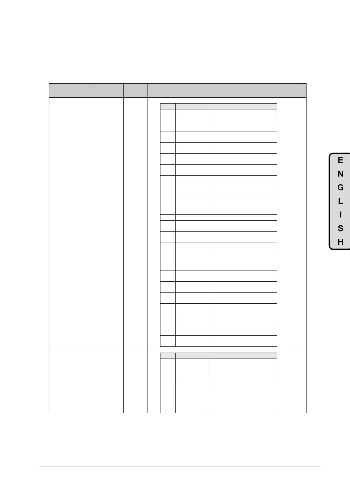
The source for comparator 1 can be set according to the following table:
OPT.
DESCRIPTION
FUNCTION
00
NONE
There is no source for the
comparator.
01
SPEED
MOTOR
Comparison signal is motor speed.
02
CURRENT
MOTOR
Motor current signal.
03
VOLTAGE
MOTOR
Motor voltage signal.
04
POWER
MOTOR
Motor power.
05
TORQUE
MOTOR
Motor torque signal.
06
PF MOTOR
Motor cosine phi
07
TEMP MOTOR
Motor temperature signal.
08
FREQUENCY
IN
Drive input frequency.
09
INPUT
VOLTAGE
Drive input voltage.
10
DC BUS
DC Bus voltage.
11
DRIVE TEMP
Drive temperature.
12
SPEED REF
Speed reference.
13
Reserved
Reserved for future use.
14
PID
REFERENCE
Speed reference in PID mode.
15
PID
FEEDBACK
System feedback signal.
16
PID ERROR
PID error. Difference between
reference and feedback signal of
the sensor.
17
ANLG INPUT 1
Signal connected to analogue input
1.
18
ANLG INPUT 2
Signal connected to analogue input
2.
19
ANLG
INPUT1+2
The average of the analogue inputs 1
and 2.
20
CURRENT
FLOW
Analogue signal proportional to the
read flow through analogue input or
pulse input.
21
MAX SCALE
We will get a maximum value,
forcing the comparator in order to
obtain the needed status.
22
ABSOLUT
SPEED
Comparison signal is motor speed
without sign (absolute value).
NO
2 COMP 1 TYPE=0
G9.1.2 /
Comparator 1
type selection
0 1
It allows selecting the operation mode of Comparator 1.
OPT.
DESCRIPTION
FUNCTION
0
Normal
Comparator will be activated when
the ON condition is given and will be
deactivated when the OFF condition
is given.
1
Window
Comparator will be activated when
signal is within the limits 1 and 2,
and additionally when limit 2 is
higher than limit 1. If limit 2 is lower
than limit 1, comparator output
logical function will be inverted.
YES

Table of Contents

Other manuals for Power Electronics SD700 Series

Questions and Answers:

Question and Answer IconNeed help?

Do you have a question about the Power Electronics SD700 Series and is the answer not in the manual?

Power Electronics SD700 Series Specifications

General IconGeneral
BrandPower Electronics
ModelSD700 Series
CategoryInverter
LanguageEnglish

Related product manuals