COMMONLY USED CONFIGURATIONS
7.3. Start / Stop Commands by Terminals and Speed
Reference by Motorized Potentiometer
7.3.1. Parameters Configuration
G1.4 / Language selection
G1.7 / Program activation
G2.1 / Motor rated current
__A (Set according to motor nameplate).
G2.2 / Motor rated voltage
__V (Set according to motor nameplate).
__kW (Set according to motor nameplate).
__rpm (Set according to motor nameplate).
__ (Set according to motor nameplate).
__Hz (Set according to motor nameplate).
G2.7 / Motor cooling at zero speed
Use the following values as a reference:
Submersible pumps and non-deflagrating motors 5%
Self-cool motor 63%
Force-cooled motor 100%
G3.1 / Speed reference source 1
PMOT Motorized potentiometer with or without reference
memory.
G4: Inputs – S4.1: Digital Inputs.
G4.1.1 / Main Control Mode
2 REMOTE (Drive control is done through control terminals).
G4.1.4 / Digital Inputs configuration
selection
4 MOTORIZED POT (It assigns the function of up and down
speed reference to two of the digital inputs. DI5 = Up (NO Contact)
and DI6 = Down (NC Contact). Reference is memorized)
5 ERASAB POT (As per above mode without memorizing the
reference).
G4.1.5 / Multi-function Digital Input 1
configuration
05 Start/Stop (Allows the start/stop command to be given by a
switch).
G5: Inputs: Acceleration and Deceleration Ramps.
G5.7 / Ramp 1 of reference increase for
motorized potentiometer
1.0% / s (Modify these ramps to tune operation). If the ramp is
increased the speed reference response will be faster. If the ramp
is decreased the speed reference response will be slower.
G5.8 / Ramp 1 of reference decrease for
motorized potentiometer
3.0% / s (Modify these ramps to tune operation). If the ramp is
increased the speed reference response will be faster. If the ramp
is decreased the speed reference response will be slower.
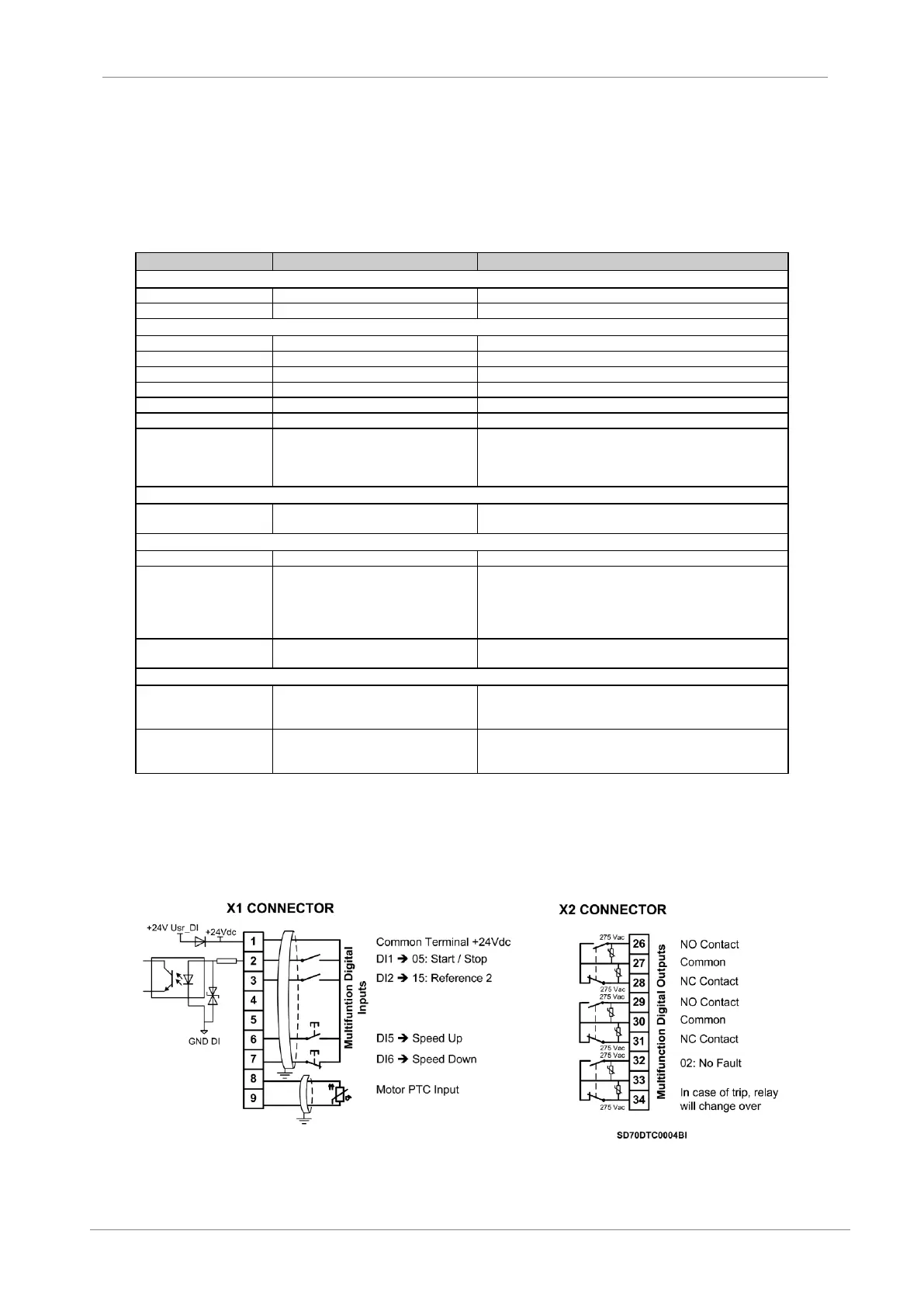
7.3.2. Connections Drawing
Terminals 1 and 2: start / stop command (NO status).
Terminals 1 and 6: up speed command (NO status).
Terminals 1 and 7: down speed command (NC status).
Figure 7.2 Start / Stop commands by terminals and speed reference by motorized potentiometer
Note: Use screened cables for the controls and connect the screen to the ground.