COMMONLY USED CONFIGURATIONS
7.4. Start / Stop Commands by Terminals and Seven Speed
References Selectable by Digital Inputs
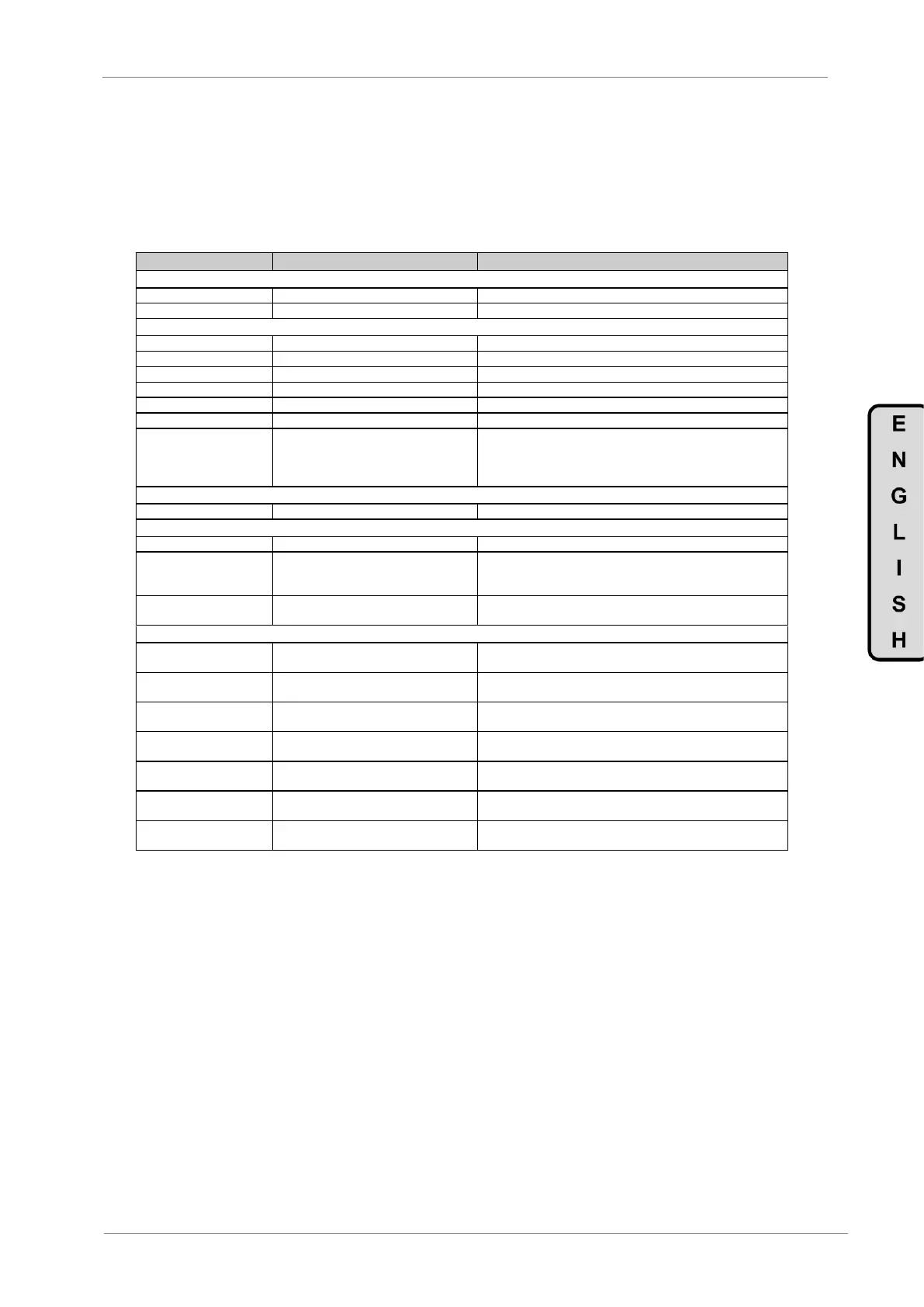
7.4.1. Parameters Configuration
G1.4 / Language selection
G1.7 / Program activation
G2.1 / Motor rated current
__A (Set according to motor nameplate).
G2.2 / Motor rated voltage
__V (Set according to motor nameplate).
__kW (Set according to motor nameplate).
__rpm (Set according to motor nameplate).
__ (Set according to motor nameplate).
__Hz (Set according to motor nameplate).
G2.7 / Motor cooling at zero speed
Use the following values as a reference:
Submersible pumps and non-deflagrating motors 5%
Self-cool motor 63%
Force-cooled motor 100%
G3.1 / Speed reference source 1
MREF Multiple speed references activated by digital inputs.
G4: Inputs – S4.1: Digital Inputs.
G4.1.1 / Main Control Mode
2 REMOTE (Drive control is done through control terminals).
G4.1.4 / Digital Inputs configuration
selection
3 MREF 3 WIRES (Automatically programs digital inputs 4, 5
and 6 as multiple speed references for up to 7 different values. The
others digital inputs remain user configurable).
G4.1.5 / Multi-function Digital Input 1
configuration
05 Start/Stop (Allows the start/stop command to be given by a
switch).
G14.1 / Multi-reference 1
+10.0% (Allows setting the setpoint 1 value for the drive. It should
be set according to the application requirements).
G14.2 / Multi-reference 2
+20.0% (Allows setting the setpoint 2 value for the drive. It should
be set according to the application requirements).
G14.3 / Multi-reference 3
+30.0% (Allows setting the setpoint 3 value for the drive. It should
be set according to the application requirements).
G14.4 / Multi-reference 4
+40.0% (Allows setting the setpoint 4 value for the drive. It should
be set according to the application requirements).
G14.5 / Multi-reference 5
+50.0% (Allows setting the setpoint 5 value for the drive. It should
be set according to the application requirements).
G14.6 / Multi-reference 6
+60.0% (Allows setting the setpoint 6 value for the drive. It should
be set according to the application requirements).
G14.7 / Multi-reference 7
+70.0% (Allows setting the setpoint 7 value for the drive. It should
be set according to the application requirements).
7.4.2. Connections Drawing
Terminals 1 and 2: start / stop command (NO status).
Terminals 1 and 5: multi-reference A (NO status).
Terminals 1 and 6: multi-reference M (NO status).
Terminals 1 and 7: multi-reference B (NO status).