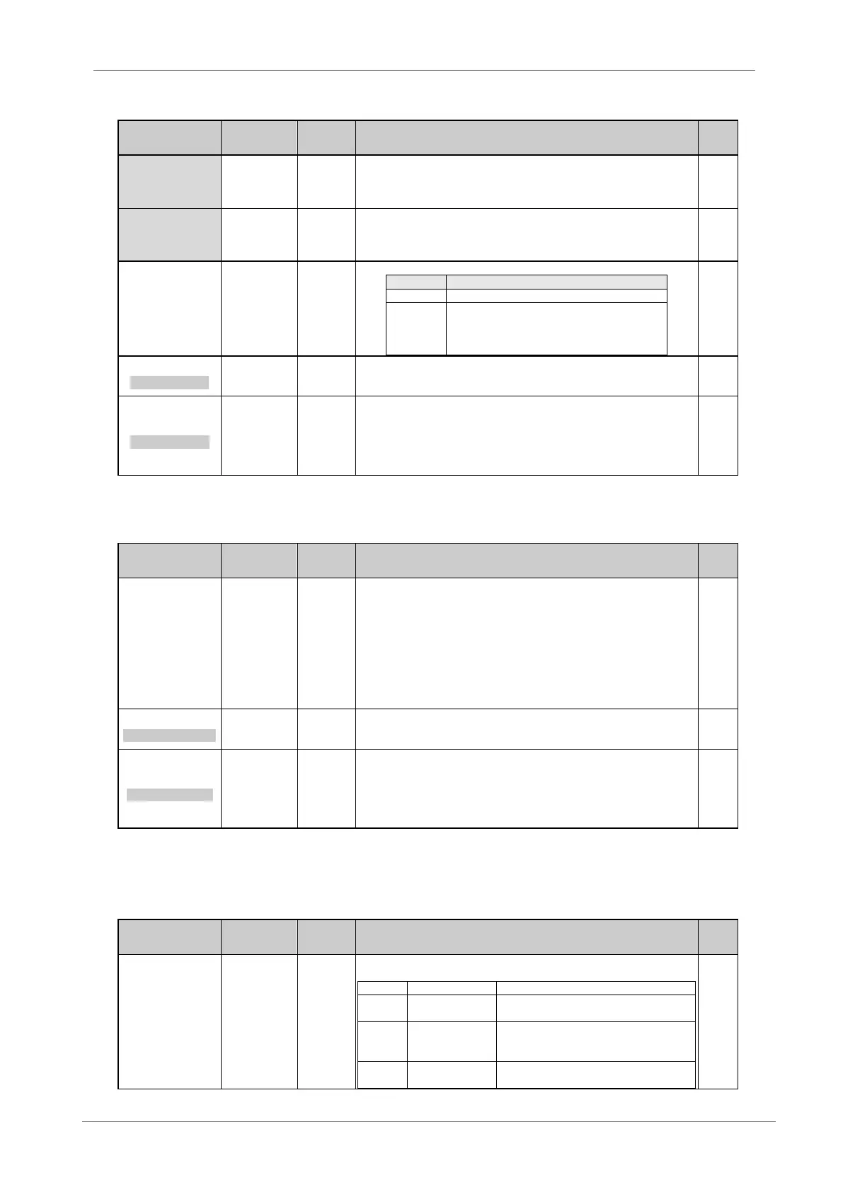
DESCRIPTION OF PROGRAMMING PARAMETERS
Parameter /
Default Value
G4.3.12 /
Maximum
operating range
of sensor
G4.3.10 to
+3200
Engineering
units
To set the maximum operating range, if the real operating range is different than
the range of the sensor which will be used as sensor in open loop. It corresponds
with the voltage or current level set in ‘G4.3.6INmin2’. This parameter should be
configured to operate with sensor in open loop.
G4.3.13 /
Maximum speed
range for sensor
in open loop
It allows setting the maximum speed range corresponding to the maximum sensor
range set in ‘G4.3.12 FA2’, when the sensor will be used in open loop.
The value is a percentage of the motor rated speed.
G4.3.14 /
Protection for
Analogue Input 2
loss
To set the drive stop mode when a loss of the analogue input 2 signal occurs.
When the analogue input level decreases down
to zero value, sensor will be considered damaged
and the drive will stop generating a fault 'F43
AIN2 LOSS'.
15 2_Z BAND=OFF
AIN2 ZERO BAND
G4.3.15 / Zero
band filter for
Analogue Input 2
Filtering of analogue input 2 signal. Setting this value we can filter analogue input
2 to avoid possible electrical noise preventing the analogue reading a zero value.
16 FILTER2=OFF
AIN2 STABIL FILT
G4.3.16 / Low
Pass filter for
Analogue Input 2
It allows filtering the Analogue Input 2 signal. Setting the value of this time
constant we can eliminate possible instabilities in the value of the same ones due
to noise, wiring faults, etc.
Note: When applying a Low Pass filter to any analogue signal, a delay time in the
own signal is generated. This delay time is the value of the configured time
constant approximately.
[4]
It will be available in case of 'G4.3.1 SENSOR 2 = Y'.
4.4.4. Subgroup 4.4 – S4.4: Pulse Input
Parameter /
Default Value
G4.4.1 / Sensor
units of Pulse
Input
%
l/s
m³/s
l/m
m³/m
l/h
m³/h
m/s
m/m
m/h
Allows selection of the units to measure the flow.
Note: To use this input you should have a flowmeter with a digital pulse output of
pulse width greater than 50ms.
Used for flow limitation algorithm. See S25.10.
2 Pls/s = 100l/s
LIQU AMOUNT/PULS
G4.4.2 /
Flowmeter
configuration
It allows setting the amount of the fluid per pulse received.
For example, if setting is ‘2Pls/s=100l/s’, and the present flow is 500l/s, 5
pulses/sec will be received.
3 M Rn=1000l/s
FLOW MAX RANGE
G4.4.3 /
Maximum range
of flow meter
It allows user to set the maximum range of the flow meter. It is used to calculate
the reset level of the flow control algorithm.
Parameter G25.10.4 is linked with the value set in this parameter. Example: If you
set a maximum range of 100 units ‘G4.4.3=100’, and the reset level of the flow
algorithm is desired below 30 units, you have to set ‘G25.10.4=30%’.
For additional information, see the ‘Pump Application Manual’ for the SD700.
4.4.5. Subgroup 4.6 – S4.6: Optic Fiber
4.4.5.1. Subgroup S4.6.1 – 1. MODO FIBRA
Parameter /
Default Value
This parameter is used to select the drive role in the optical fiber network. We can
select three options:
The equipment will make the functions of
master in the network
The equipment will act as a slave, taking
orders of the master and transmitting its
status
The equipment will be independent in the
network, it hasn’t slave or master function.