1. DISPLAY UNIT AND CONTROL KEYPAD
1.1. Keypad Unit Description
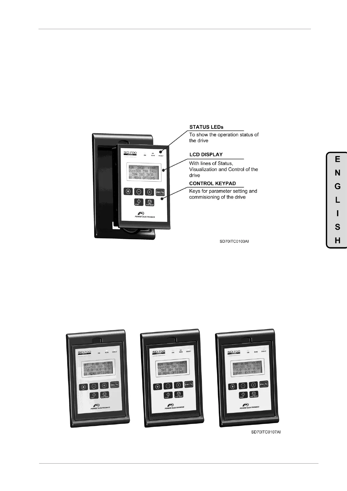
The display of the SD700 is removable for remote installation, as the illustration shows. There are
three leds on the display which indicate the drive operational status, one LCD screen with 4 lines of
16 characters each and keys for control and parameter setting.
Figure 1.1 Display Unit and Keypad
1.1.1. LEDs for Status Indication
Leds offer an easy method of identifying if the SD700 is powered up, if the drive is supplying
output voltage, or if the drive has tripped.
Led ON: Yellow colour. When it is lit, indicates equipment is powered up. When it is blinking,
indicates the drive gets any warning.
Led RUN: Green colour. When it is lit, indicates the motor is powered by the SD700.
Led FAULT: Red colour. When it is blinking, indicates the equipment is in fault status.
Figure 1.2 Status Visualization