DESCRIPTION OF PROGRAMMING PARAMETERS
Parameter /
Default Value
G8.1.1 /
Selection of
Relay 1 control
source
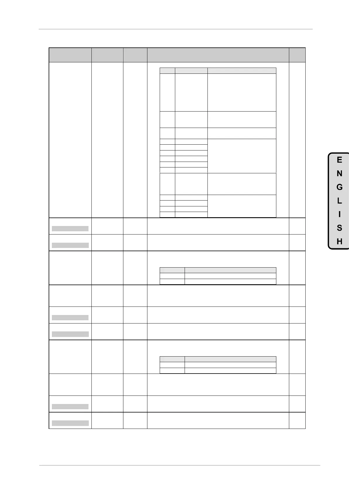
Note: Coming from the previous page.
The relay will be activated like in
option “05 RUN”, considering the
ON delay time set in G8.1.2, G8.1.6
or G8.1.10 (depending on the used
Relay 1, 2 or 3), and will be
deactivated when the motor speed
is below the speed set in G8.1.13.
In pump application the relay is
energized when the application
state is pipe filling.
The relay is energized when there is
any Warning.
Copies the corresponding digital
input and closes the relay when the
digital input is active.
If this option is selected in one
digital output, when the drive trips
by the F40 PTC EXT, the digital
output will change the status.
It will be active when the respective
fault configured in G8.1 group
FAULTX is raised in the drive.
2 T R1 ON=0.0s
R1 ACTIVAT DELAY
G8.1.2 / ON
delay time for
Relay 1
Allows user to set a delay time before activating relay 1.
If during this ON delay time the activation condition disappears, the relay will not
be activated.
3 T R1 OFF=0.0s
R1 DEACTIV DELAY
G8.1.3 / OFF
delay time for
Relay 1
Allows user to set a delay time before deactivating relay 1.
If during this OFF delay time the deactivation condition disappears, the relay will
follow activated.
G8.1.4 / Relay 1
inversion
It allows user to invert the logic of relay 1 functionality.
Relay 1 has one normally open contact (connection 26/27) and another normally
close contact (connection 27/28).
Inversion of relay logical function.
G8.1.5 /
Selection of
Relay 2 control
source
Note: See parameter function of G8.1.1.
6 T R2 ON=0.0s
R2 ACTIVAT DELAY
G8.1.6 / ON
delay time for
Relay 2
Allows user to set a delay time before activating relay 2.
If during this ON delay time the activation condition disappears, the relay will not
be activated.
7 T R2 OFF=0.0s
R2 DEACTIV DELAY
G8.1.7 / OFF
delay time for
Relay 2
Allows user to set a delay time before deactivating relay 2.
If during this OFF delay time the deactivation condition disappears, the relay will
follow activated.
G8.1.8 / Relay 2
inversion
It allows user to invert the logic of relay 2 functionality.
Relay 2 has one normally open contact (connection 29/30) and another normally
close contact (connection 30/31).
Inversion of relay logical function.
G8.1.9 /
Selection of
Relay 3 control
source
Note: See parameter function of G8.1.1.
10 T R3 ON=0.0s
R3 ACTIVAT DELAY
G8.1.10 / ON
delay time for
Relay 3
Allows user to set a delay time before activating relay 3.
If during this ON delay time the activation condition disappears, the relay will not
be activated.
11 T R3 OFF=0.0s
R3 DEACTIV DELAY
G8.1.11 / OFF
delay time for
Relay 3
Allows user to set a delay time before deactivating relay 3.
If during this OFF delay time the deactivation condition disappears, the relay will
follow activated.