DESCRIPTION OF PROGRAMMING PARAMETERS
Parameter /
Default Value
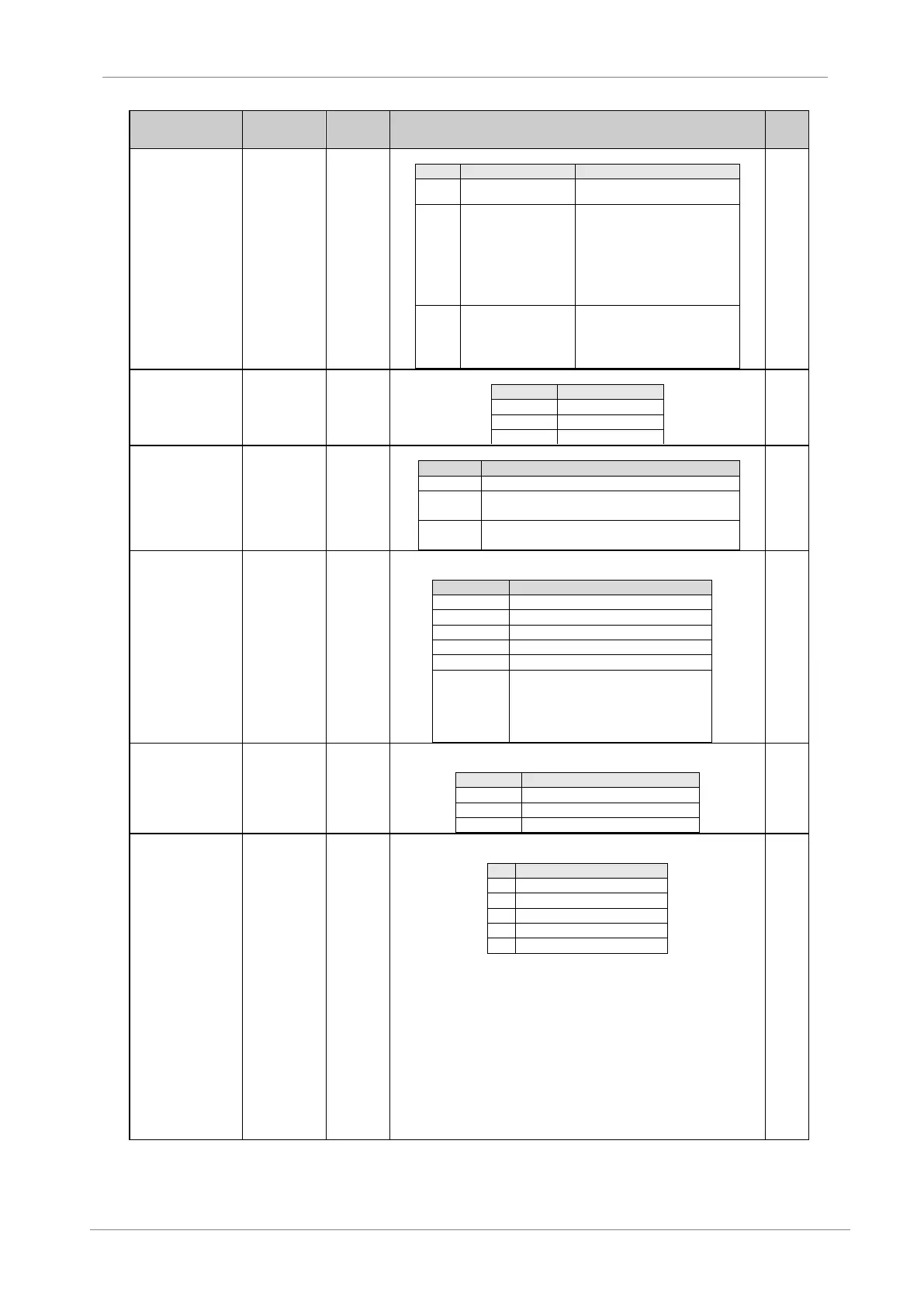
The following table shows the different control modes
The drive control is given in [G4.1.1]
or [G4.1.2] parameter
If the Control Mode 1 parameter
[G4.1.1] is active and set to 3
(Comm.), then the drive is operated
through DeviceNet. Identically, when
Control Mode 2 is active, the value
contained in [G4.1.2] parameter
determines the way it is finally
controlled.
The PLC will decide how the drive is
controlled. If it is controlled over
network, option 1 will be enabled.
However, if the net resigns control, it
will be controlled locally.
G20.4.4 /
Reference
modes
The following table shows the different reference modes.
It is used to select what has to do the drive in case of communication fault:
Drive trips by fault F60.
The drive keeps operating despite communication
loss.
While the communication wire is not well connected,
the drive still tripping.
It is used to select, which input instance of the assembly object is to be used for
the default data production of IO connection.
Power Electronics Basic Status
Power Electronics Extended Status
Power Electronics medium status
Power Electronics customized status.
The two first bytes are status bytes and
the next nine registers are selectable.
Configurable in parameters SV20.6.1 to
SV20.6.9.
G20.4.7 / Output
assembly
It is used to select, which output instance of the assembly object is to be used for
the default data consumption of the IO connection
Power Electronics Basic Control
G20.4.8 /
DeviceNet State
It is a read-only parameter, which value indicates the current state of DeviceNet
communications.
On a switch on, the drive automatically enters into the MAC_ID_Duplicated check
state. After the successful response to the duplicated MAC ID request messages
(2 messages), the drive will enter into the Online state. There, the drive is ready to
communicate within DeviceNet network by mean of explicit and I/O messages.
If the drive receives any duplicate MAC ID response message, while in Online
state, it will switch over to Communications_Fault state. The drive will recover
from this communication-faulted state by means of the offline connection set
mechanism.
The SD700 DeviceNet stack can communicate with the other DeviceNet node
which is present in the DeviceNet network through explicit or cyclic I/O messages.
(*) Note: Available if G20.0.1 = 5 DeviceNet