21
X8 | SERVICE MANUAL
INDEX
(Fig. 29)
(Fig. 30)
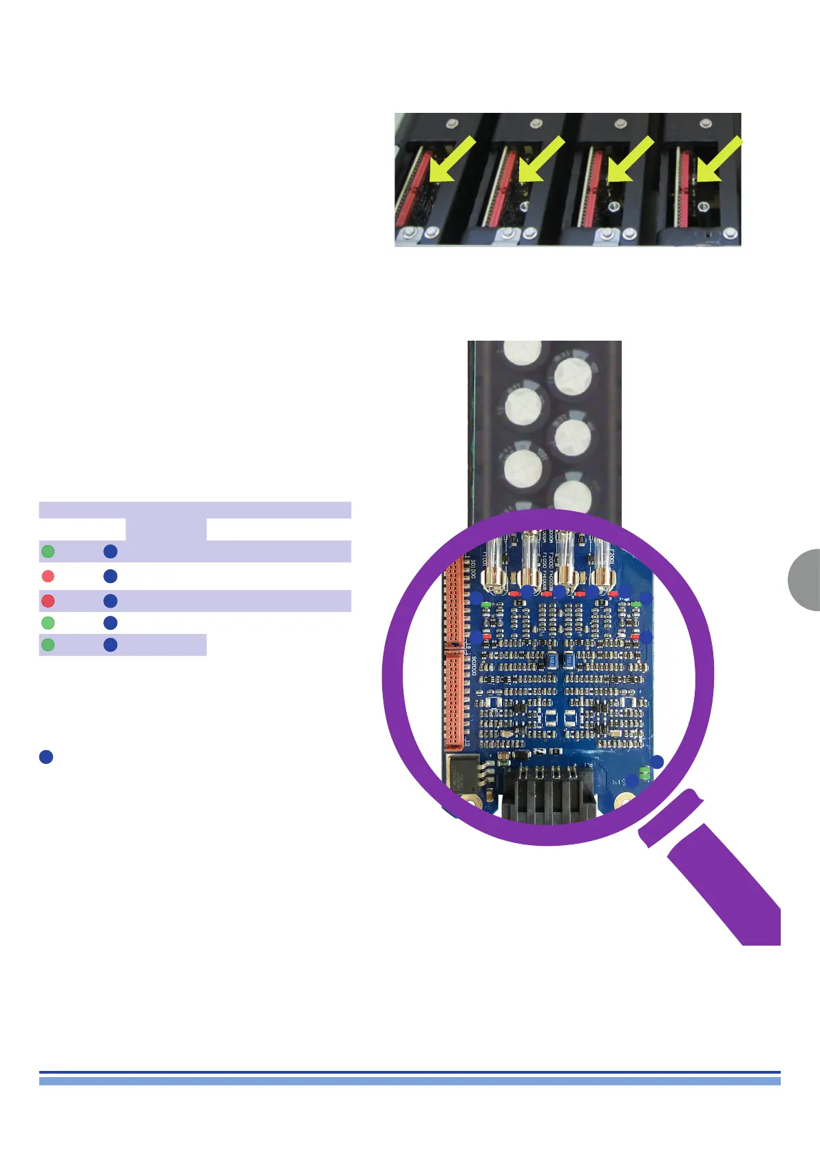
9.Amp Modules Verification
Each Audio Module features 10 check LEDs, as
highlighted on (Fig. 30).
In normal conditions, only the 4 Green LEDs are on.
In case of malfunction, the Red LEDs will indicate that
the module is in protection mode and replacement is
necessary.
Checking the module’s diagnostic LEDs is quite tricky,
since it is impossible (and extremely dangerous) to have
the AMP Modules on whilst not properly inserted in the
chassis.
By angling your sight in the direction portrayed on (Fig.
29) you should be able to see if any of the 10 Diagnostic
LEDs are glowing red.
Refer to (Fig. 24) in order to assess the status of the Amp
Module.
*Another set of LED is placed next to the fuses. (marked
C
on g. 24)
These LEDs will shine a red light when the corresponding
fuse is open (blown).
Prior to replacing the fuse, check it with a multimeter set
to ohm.
A A
C C C C
B B
E
D
NORMAL
OPERATING
CONDITIONS
STATUS
Color REF ON OFF
Green
A
ON OK FAILURE
Red
B
OFF
CH in
protection
OK
Red
C
OFF OPEN FUSE* OK
Green
D
ON
+/-15V aux OK FAILURE
Green
E
ON