INDEX
22
X8 | SERVICE MANUAL
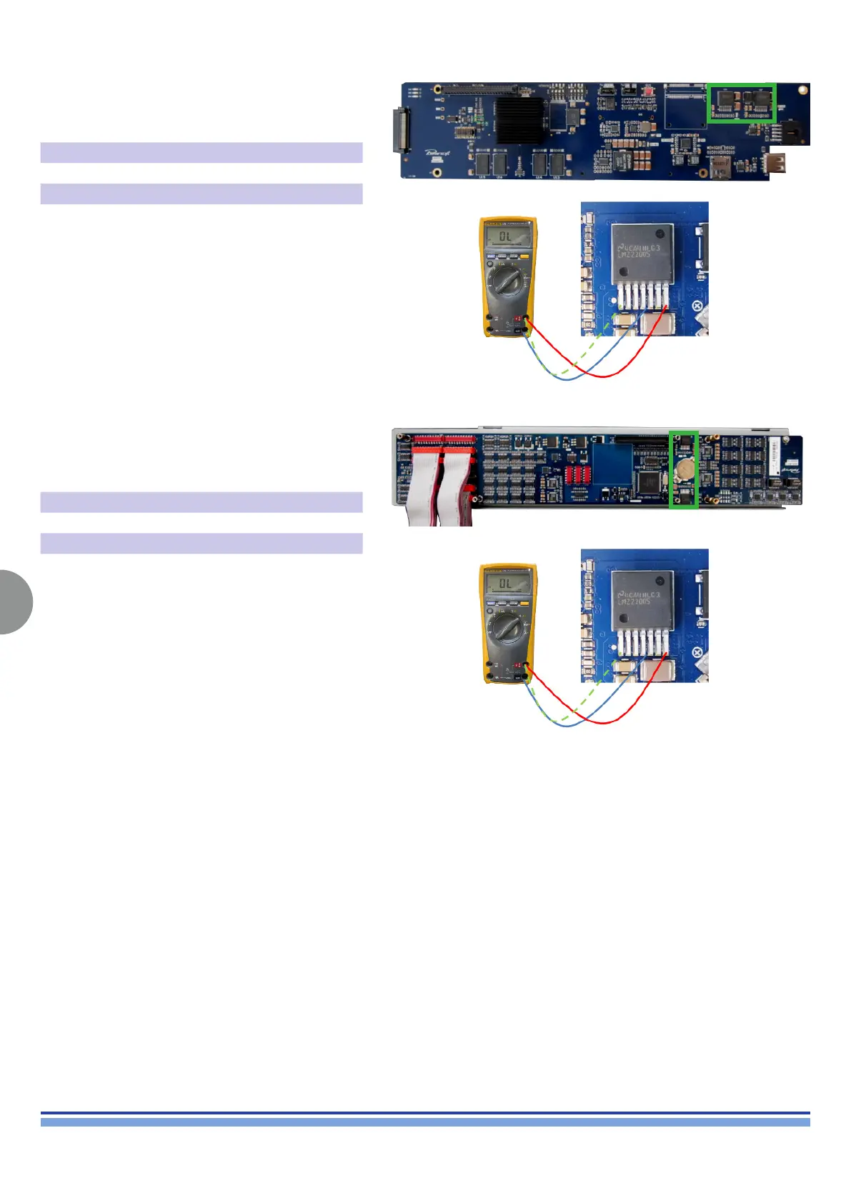
(Fig. 31)
(Fig. 33)
(Fig. 32)
(Fig. 33)
Focusing the attention on U29 and U27, as portrayed on
(Fig. 31), check the resistance between pins 4-7 and 1-7.
(Fig. 32)
IC PIN Resistance
U29 1-7 5K (approx.)
U27 4-7 3K (approx.)
In case of any short, replace the board.
Focusing the attention on U51 and U52, as portrayed on
(Fig. 32), check the resistance between pins 4-7 and 1-7.
(Fig 33)
IC PIN Resistance
U51 1-7 12K (approx.)
U52 4-7 500 (approx.)
In case of any short, replace the board.