20
X8 | SERVICE MANUAL
INDEX
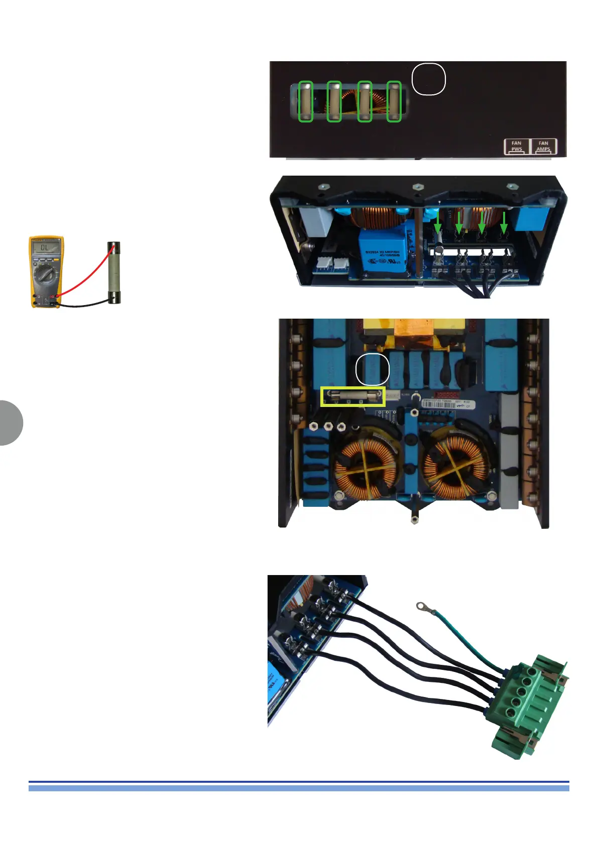
Replacing the Fuses:
Remove The Power Supply.
Discharge the capacitor’s bank.
Place the module on an at surface and gently press on
the fuses in order to release them from their slot. (Fig. 25)
(Fig. 25)
(Fig. 26)
(Fig. 27)
(Fig. 28)
Lay the Module upside down so that the fuse end
protrudes from the edge of the stand, thus leaving some
operating room on the bottom of the module itself.
Set the fuses in place. (Fig. 26)
Check the fuses with a multimeter.
(Fig. 27) Portrays the location of Fuse B.
Remove the fuse from its housing and check it with a
multimeter as for the previous test.
Internal Mains Connection:
Portrayed on (Fig. 28) is the wiring between the Power
Supply module and the Mains Connector.
Use this picture as a reference when resetting the Mains
Connector.
A
B