14
X8 | SERVICE MANUAL
INDEX
6. Removing the DIGI and ADLINK Boards
• Extract all the audio modules.
• Remove the Dante Board.
• Remove the Wi-Fi Module
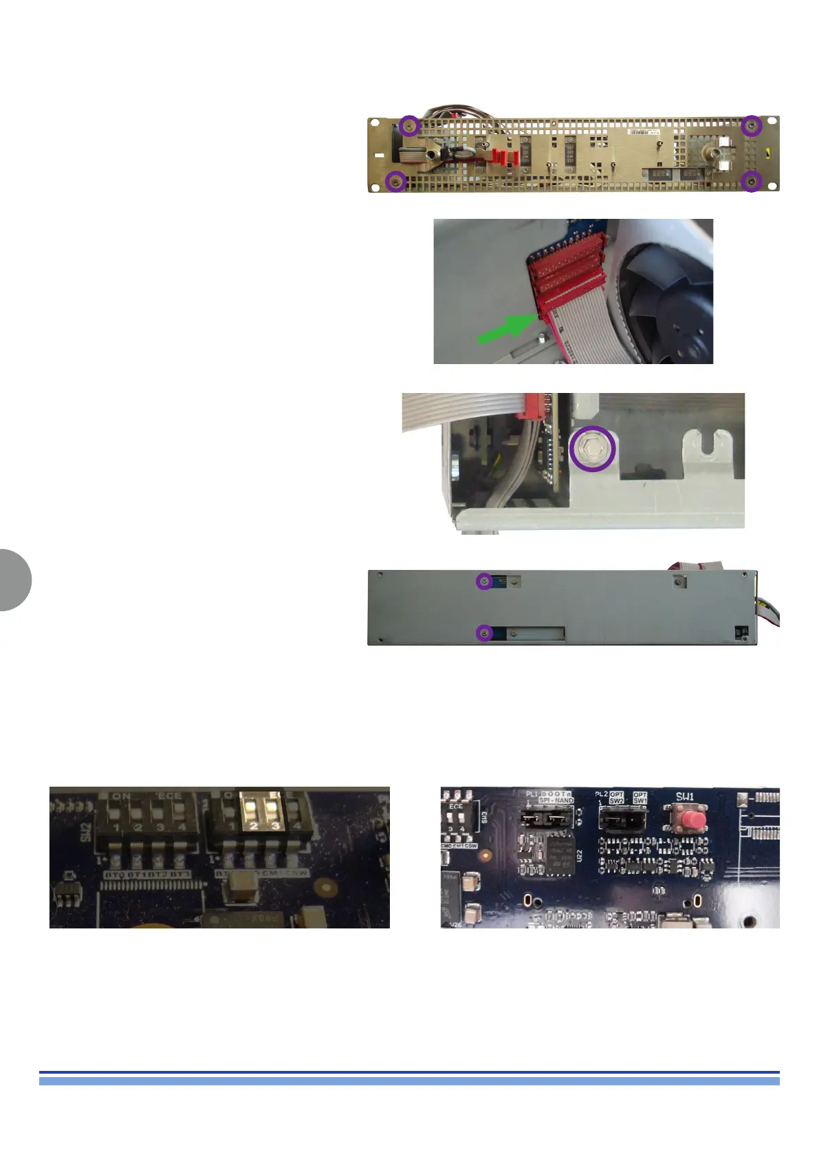
Remove the front mesh panel by unscrewing the 4 T20
Torx screws highlighted on (Fig. 15)
(Fig. 15)
Unplug the micromatch connectors portrayed on (Fig. 16)
(Fig. 16)
(Fig. 17)
Unscrew the screw highlighted on (Fig. 17) by means of a
M5 Socketed screwdriver.
(Fig. 18)
Unscrew the screws highlighted on (Fig. 18) by means of
a T10 Torx Screwdriver
Carefully extract the DIGI/ADLINK boards assembly.
Older productions feature the Brooklyn II board.
The CM0 and CM1 dip switches must be on the “ON” Position
This picture shows the default configuration of the jumpers
on the DIGI board. NEVER PRESS THE RED BUTTON!