DESCRIPTION:
DATE:
DRAWING NO:
6of17
SHEET:
REVI SION:
L
NOTE:
Callout letter
and
map to drawing #164201300---6
,,,
041503
A
B
C
D
164201300---1
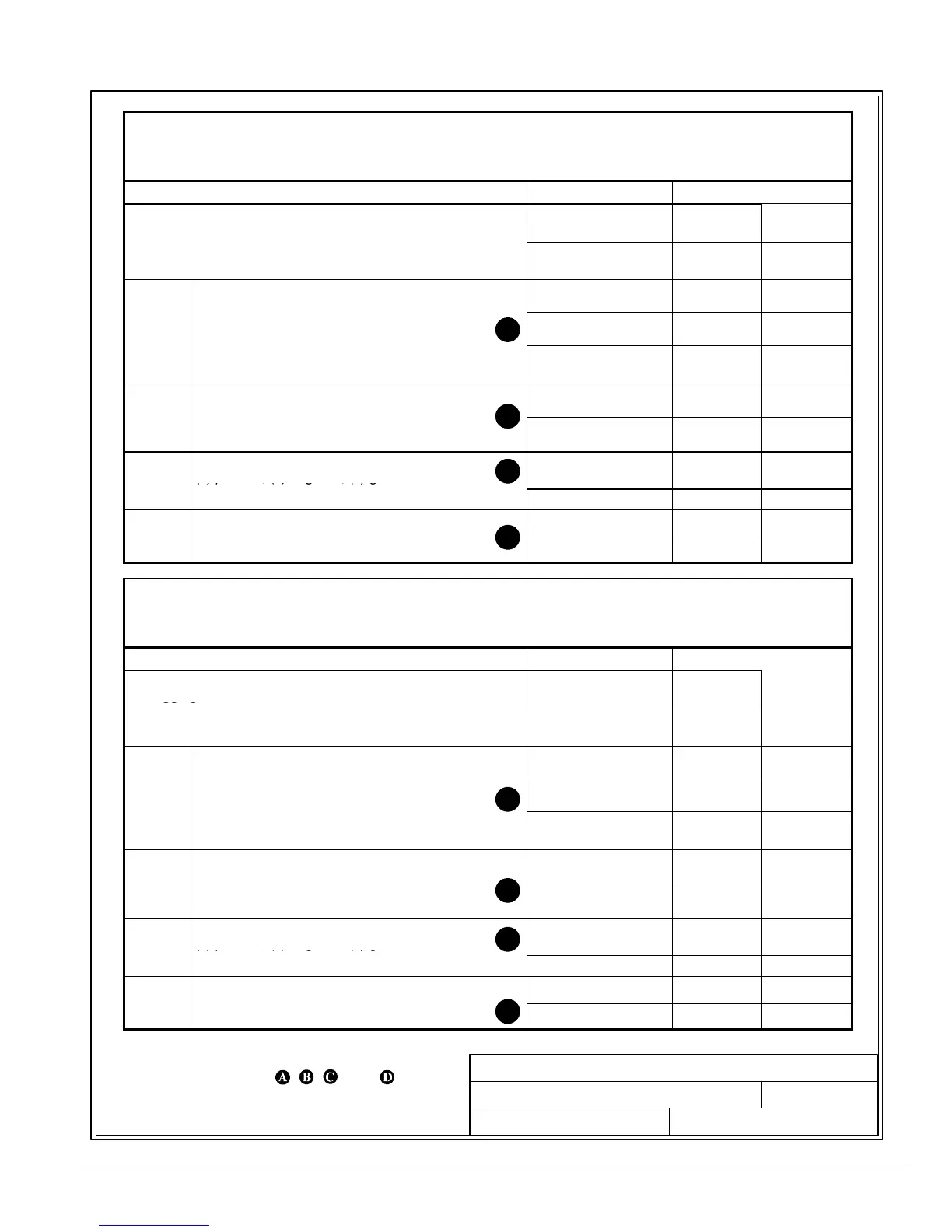
POWER WIRING INSTALLATION NOTES
A
B
C
D
A---7
Powerware 9330 (10 kVA--40 kVA) Installation and Operation
164201300 Rev . N 013004
Table I. INPUT/OUTPUT Ratings & External Wiring Requirements for
Po werw are 9330---40/35
(Without Options Cabinet)
Ratings
Units Rating 50/60 Hz
Basic unit ratings at
0.7 lagging PF load
KVA
KW
35
24.5
35
24.5
INPUT/OUTPUT
VOLTAGE
208 220
CIn
ut to UPS Rectifier
0.95min.PF
C
.
.
3
1
mps* 92 87.5
INPUT
,
Minimum conductor size (number per )
AWG or kcmil(ea) 2(1) 2(1)
*(Maximum amps includes full load current plus
battery recharge current)
C
AC Input to Module Bypass (UPS Bypass)
Full Loa
Cu
en
3, (1) Neutral, (1) gnd
Amps
97 92
INPUT
,
,
Minimum conductor size (number per )
AWG or kcmil(ea) 1(1) 1(1)
DC
DC Input from External Battery Source to UPS
(1) positive, (1) negative, (1) gnd
VDC (Nominal)
Amps
288
91
288
91
INPUT
Minimum conductor size (number per pole) (See note 8)
AWG or kcmil(ea) 2(1) 2(1)
C
AC Output to Critical Load
Amps 97 92
OUTPUT
ull Loa
u
e
t3
,
1) Neut
al,
1) g
Minimum conductor size (number per )
AWG or kcmil(ea) 1(1) 1(1)
Table J. INPUT/OUTPUT Ratings & External Wiring Requirements for
Po werw are 9330---40/40
(Without Options Cabinet)
Ratings
Units Rating 50/60 Hz
Basic unit ratings at
0.7 lagging PF load
KVA
KW
40
28
40
28
INPUT/OUTPUT
VOLTAGE
208 220
CIn
ut to UPS Rectifier
0.95min.PF
C
.
.
3
1
mps* 100 98
INPUT
,
Minimum conductor size (number per )
AWG or kcmil(ea) 1(1) 1(1)
*(Maximum amps includes full load current plus
battery recharge current)
C
AC Input to Module Bypass (UPS Bypass)
Full Loa
Cu
en
3, (1) Neutral, (1) gnd
Amps
111 105
INPUT
,
,
Minimum conductor size (number per )
AWG or kcmil(ea) 1/0 (1) 1/0 (1)
DC
DC Input from External Battery Source to UPS
(1) positive, (1) negative, (1) gnd
VDC (Nominal)
Amps
288
100
288
100
INPUT
Minimum conductor size (number per pole) (See note 8)
AWG or kcmil(ea) 1(1) 1(1)
C
AC Output to Critical Load
Amps 111 105
OUTPUT
ull Loa
u
e
t3
,
1) Neut
al,
1) g
Minimum conductor size (number per )
AWG or kcmil(ea) 1/0 (1) 1/0 (1)