DESCRIPTION:
DATE:
DRAWING NO:
7of17
SHEET:
REVI SION:
L
NOTE:
Callout letter
and
map to drawing #164201300---6
,,,
041503
A
B
POWER WIRING INSTALLATION NOTES
164201300---1
A --- 8
Powerware 9330 (10 kVA--40 kVA) Installation and Operation
164201300 Rev . N 013004
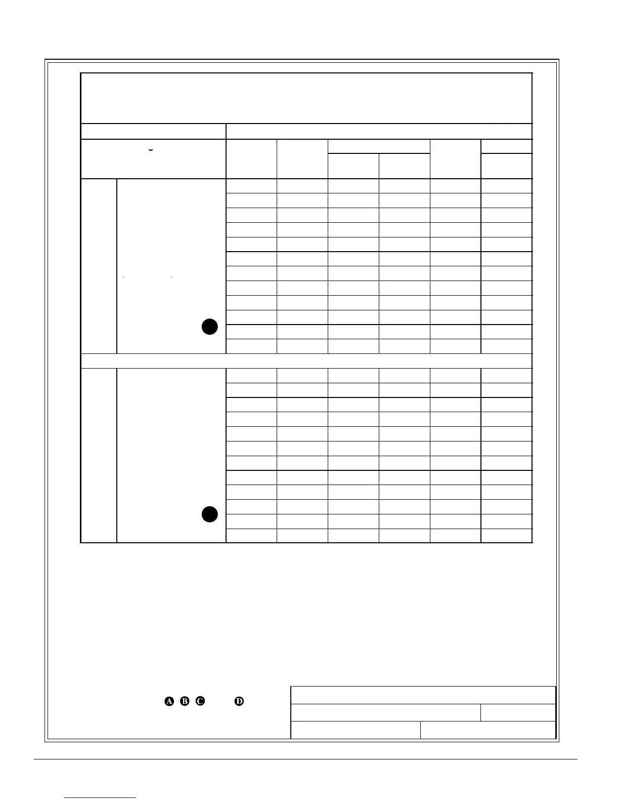
Table K. Ratings & External Wiring Requirements for
Po werwar e 9330 (25 kVA---40 kV A)
Opt ions Cabin e t INP U T and B Y PASS Trans for m er s
Ratings 50/60 Hz
Basic unit ratings at Voltage
Conductor
0.7 lagging PF load
Series/
Model
kVA/KW
Input Output
npu
Current
(Amps)
Minimum
Size
40/25 25/17.5 208 208 69.4 4
40/25 25/17.5 480 208 30 8
40/25 25/17.5 600 208 24 10
40/30 30/21 208 208 83 2
40/30 30/21 480 208 36 8
C
C Input to UPS Rectifier
Transformer
40/30 30/21 600 208 28.8 10
INPUT
(0.95min.PF)
40/35 35/24.5 208 208 97 1
3,1gnd
40/35 35/24.5 480 208 42 6
40/35 35/24.5 600 208 33.6 8
40/40 40/28 208 208 111 1/0
40/40 40/28 480 208 48 6
40/40 40/28 600 208 38.5 8
40/25 25/17.5 208 208 69.4 4
40/25 25/17.5 480 208 30 8
40/25 25/17.5 600 208 24 10
40/30 30/21 208 208 83 2
40/30 30/21 480 208 36 8
C
C Input to UPS Bypass
Transformer
40/30 30/21 600 208 28.8 10
INPUT
Full Load Current
40/35 35/24.5 208 208 97 1
3, 1 Neutral, 1 gnd
40/35 35/24.5 480 208 42 6
40/35 35/24.5 600 208 33.6 8
40/40 40/28 208 208 111 1/0
40/40 40/28 480 208 48 6
40/40 40/28 600 208 33.5 8