4.
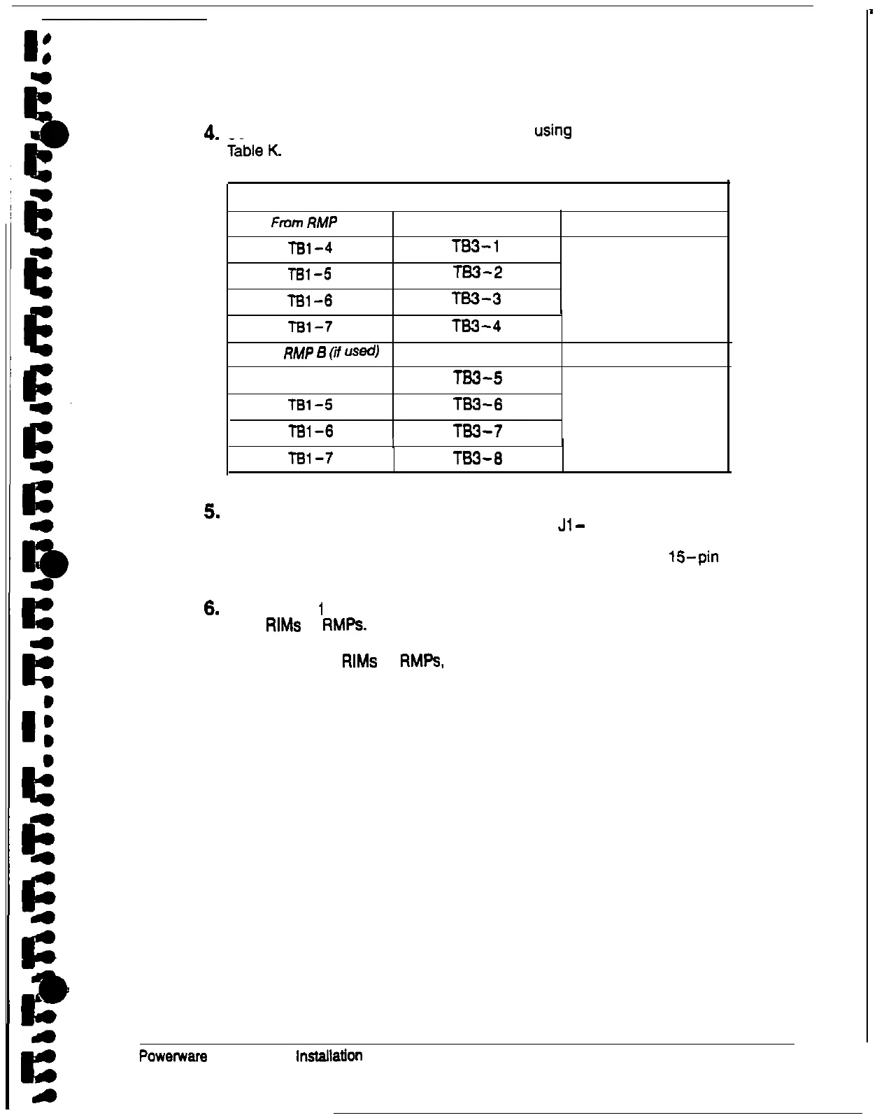
Connect the RMP wiring to the terminal block
using
the terminations shown in
Table K. RIM Wire Terminations
From
RMP
A
To UPS
Remarks
TBl-4
TB3-1
TBl-5
TS3-2
T81-6 TB3-3
TWISTED WIRES (4)
1-2 TURNS PER
3
INCHES
TBl-7
From
RMP
6
(if
US@
l-81 -4
TBl-5
TBl-6
TS3-4
To UPS
TB3-5
TS3-6
TS3-7
Remarks
TWISTED WIRES (4)
l-2 TURNS PER
3
INCHES
I
Ted-7
TB3-8
5.
Contact your local field service office for verification and testing of the RIM and
its connections prior to making connections with
Jl
-
J4.
You can order interface cables separately for connecting to the
15pin
D-sub
connectors.
6.
Repeat steps
1
through 6 for each RIM you are installing. You can install up to
three
RIMS
or RMPs.
7. After installing all
RIMS
or
RMPs,
secure the UPS cabinet by reversing all steps
of the procedure used to prepare the UPS (see page 19).
Powetware
Plus 60 UPS
lnStallalion
Manual
59