5.
If you are not installing caster assemblies, move the UPS cabinet to its final
installation site. If you are going to install the caster assemblies, move the UPS
cabinet to an open area near the installation site. Using the pallet jack or forklift,
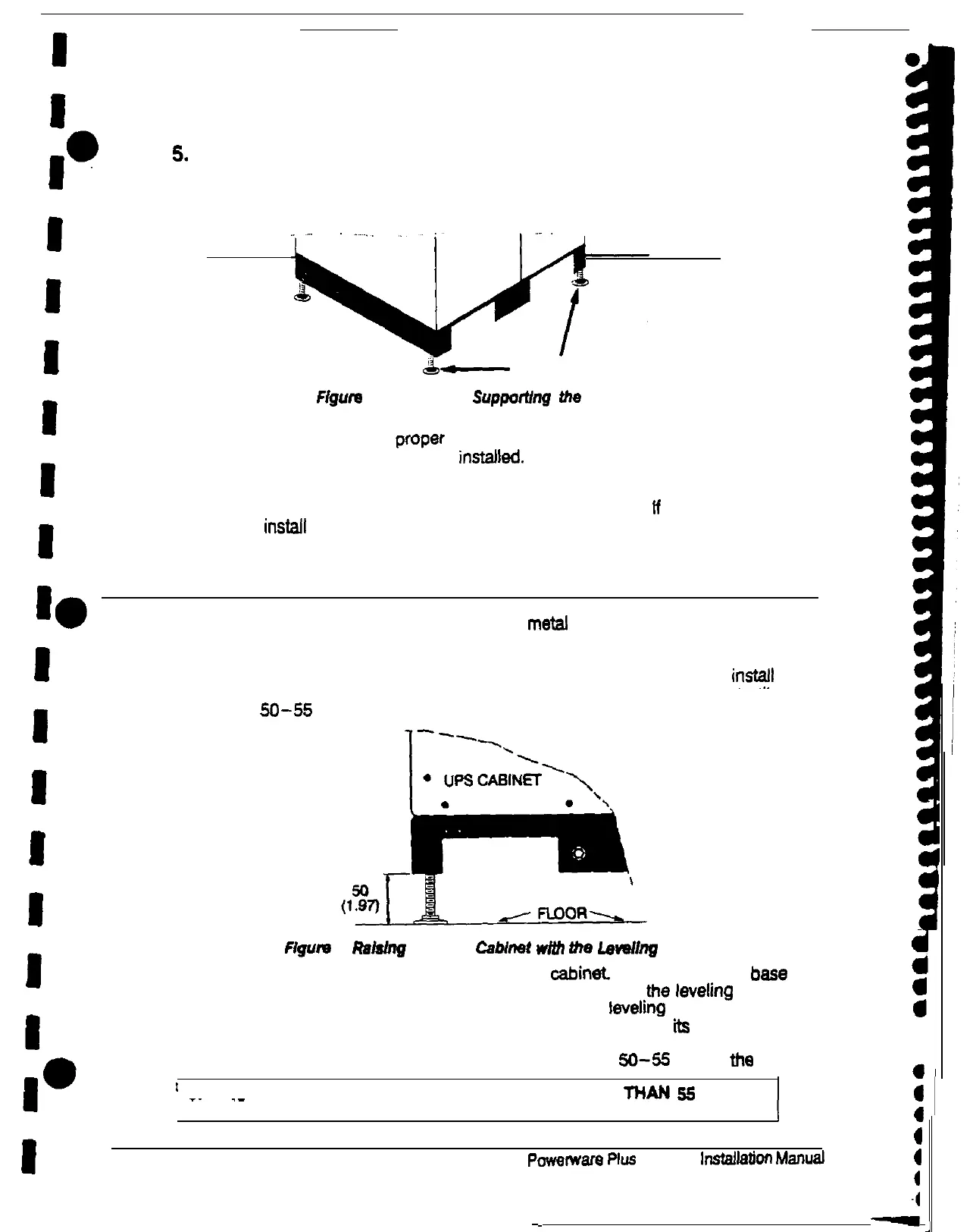
lower the cabinet until it is resting on its leveling feet (see Figure 5).
&-
LEVELING FEET
Figure
5. Leveling Feet
SupporVng
the
Cabinet
There is one leveling foot on each comer of the base of the cabinet.
The
leveling feet are set to the proper height to join the cabinets together if the
optional caster assemblies are not instaf)ed.
6.
Slide out the forks of the pallet jack or forklift and move it away from me cabinet
Use the following procedure to install the caster assemblies. ff you are not
going to install me caster assemblies, skip to ‘Preparing me UPS for Installing
Battery Cabinets” on page 17.
Installing the Caster Assemblies (optional)
Each caster assembly consists of a rectangular metal frame holding three casters.
The caster assemblies should be installed in the two forklii openings on the
bottom of the cabinet The nuts and lo&washers for bolting the caster assemblies
to the cabinet are in a manila envelope inside me cabinet Before you can instaft
the caster assemblies, you must adjust the leveling feet to raise the cabinet until
the base is
XI-55
mm off the floor (see Figure 6).
Figurn
6
Rakhg
the UPS
Cabinet
WIUI
the
Leveling
Feet
The leveling feet are threaded into me base of me cabinat. Attached near the bass
of each leveling foot is a hex nut you can turn to raise or lower
,the
levelrng foot
Starting at one comer of the cabinet. turn me hex nut of a levelrng foot clockwise
for one turn of me wrench. Move to the next leveling foot and turn
fts
hex nut one
turn clockwise.’ Work your way around me cabinet, raising each leveling foot by
one turn of the wrench. until the base of the UPS cabinet is
Xi-55
mm off me floor.
’
CAUTION: DO NOT RAISE THE UPS CABINET HIGHER THAN
55
MM
j
a
a
a
_.
.-
OFF THE FLOOR.
J
4
4
I
14
Powerware
Plus
so UPS
installation
Manual
4
4
-4
-
-