The Customer
Interfke
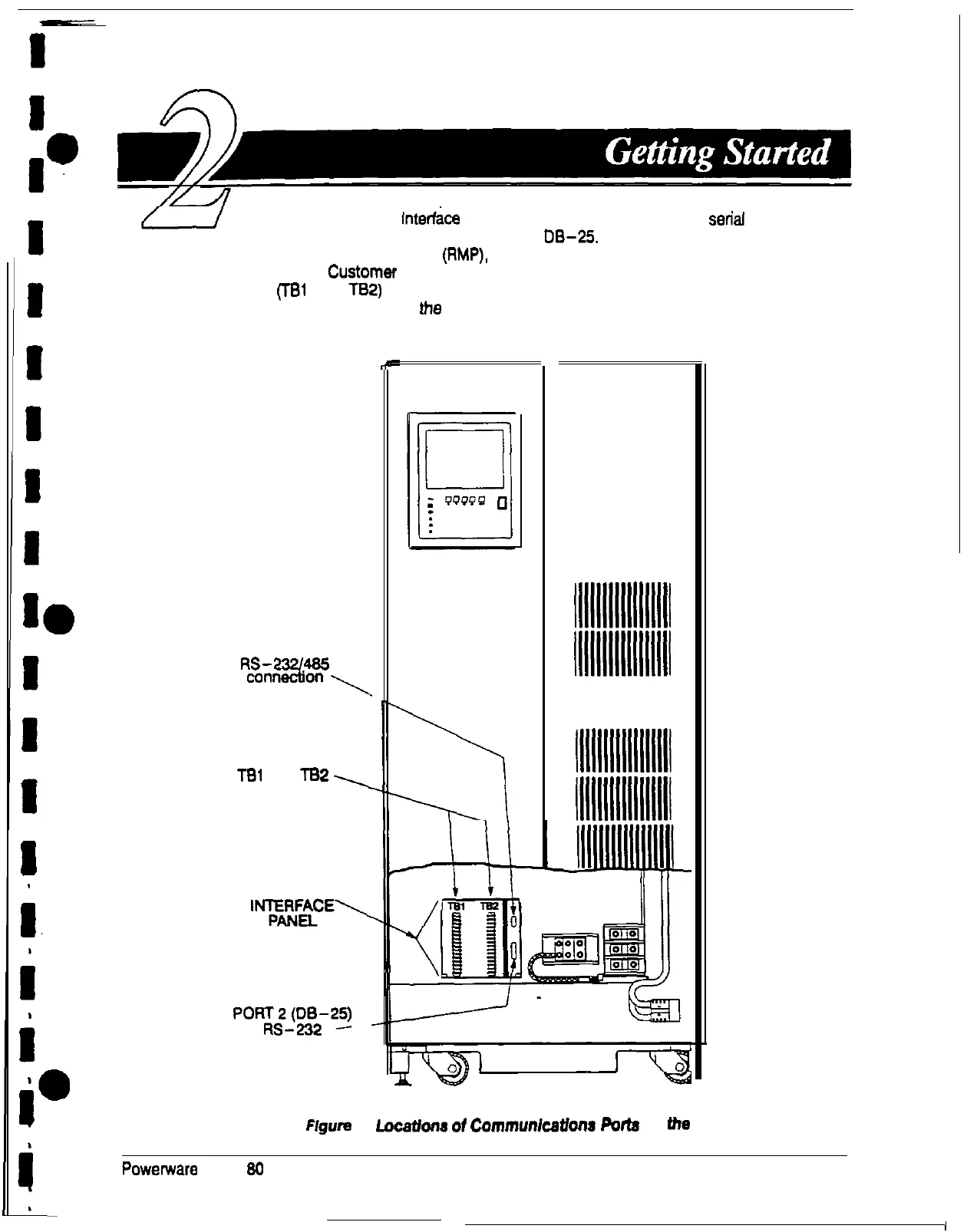
Panel inside the UPS contains two serial
communications ports, one DE-9 and one
0%25.
The ports provide a computer
interface to a remote monitor panel (RMP), relay interface module (RIM), or remote terminal
and/or printer. The
CustOmer
Interface Panel also contains two output breaker
panelboards (Tel and T82) for connecting your equipment to the UPS. Figure 1 shows
the location of these items inside the UPS.
PORT 1 (DE-9)
%EYi%~
TBl
and
TB2,
CUSTOMER
‘%F2E’
po;vg2-w
connection
P
lllllllllllllllll
lllllllllllllllll
lllllllllllllllll
lllllllllllllllll
11111111111111111
11111111111111111
lllllllllllllllll
11111111111111111
lllllllllllllllli
Figure
1.
Locatbns
ot
Communlcatlona
Potts
on
the
UPS
Powerware Plus
90
UPS Communications
3