1
I
Ia
I
I
1
I
I
I
I
1.
I
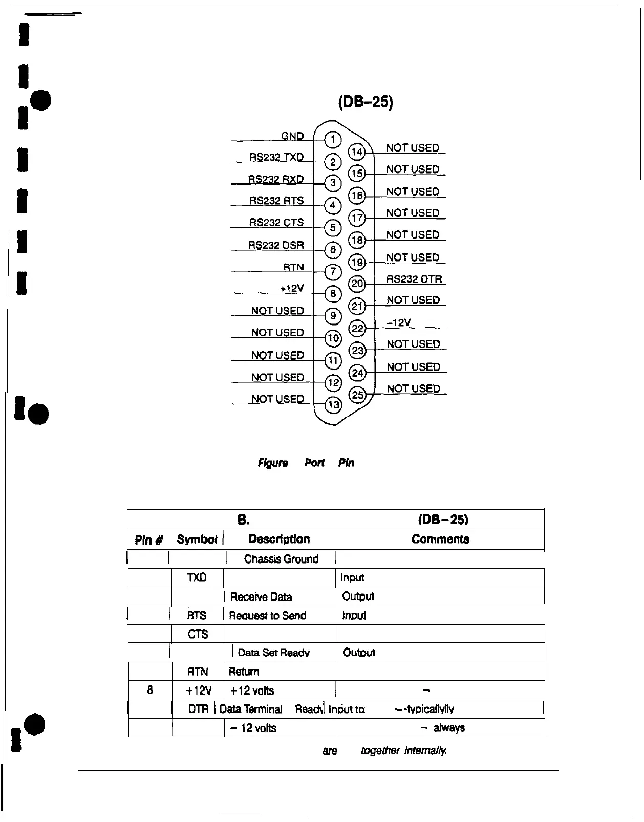
PORT 2
(DE-25)
Figure
3.
Port
2
Pb
Assignments
Table
6.
Pin Assignments for Port 2
(DE-23
I
Pin#
I
SYInboll
Deecdptlon
I
Commenta
1 1 1 GND 1
ChassisGround
1
2 TXD Transmit Data Input to UPS
3
RXD 1
ReceiveData
I Output from UPS
1
4 1
tiS
IReauasttoSend
I lnrwt to UPS
5
CTS Clear to Send
Output from UPS
6 1 DSR
IDataSetReady
I
Outwt
from UPS
77
RTNRTN ReturnReturn
aa
+12v+12v +12volts+12volts
1
Output from UPS
-
always trueOutput from UPS
-
always true
20 DTR Data Terminal Readv
lnwt
to UPS
-
tvDicallv not used by UPS
1 20 1
DTR
1
DataTerminal
Readv 1
lnwtto
UPS
-
tvDicallv
not used by UPS 1
22
(
-12v
-
12volts
Output from UPS
-
always true
I
NOTE:
Pins 5 and 6 am tied together internal&
Power-ware Plus 80 UPS Communications
5