360 Adjustments
47
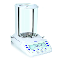
3.3 Adjusting the symmetry
1. Ensure the balance is levelled and set to the factory mode according to chapter 3.2.
2. Connect the connecting cable [16] to the symmetry pin header S1.
3. Release the display board and shift it slightly towards the bubble level.
Important:
Protect the
display board balance sided with a non static insulation against short circuits!
4. Connect the voltmeter to the connecting cable.
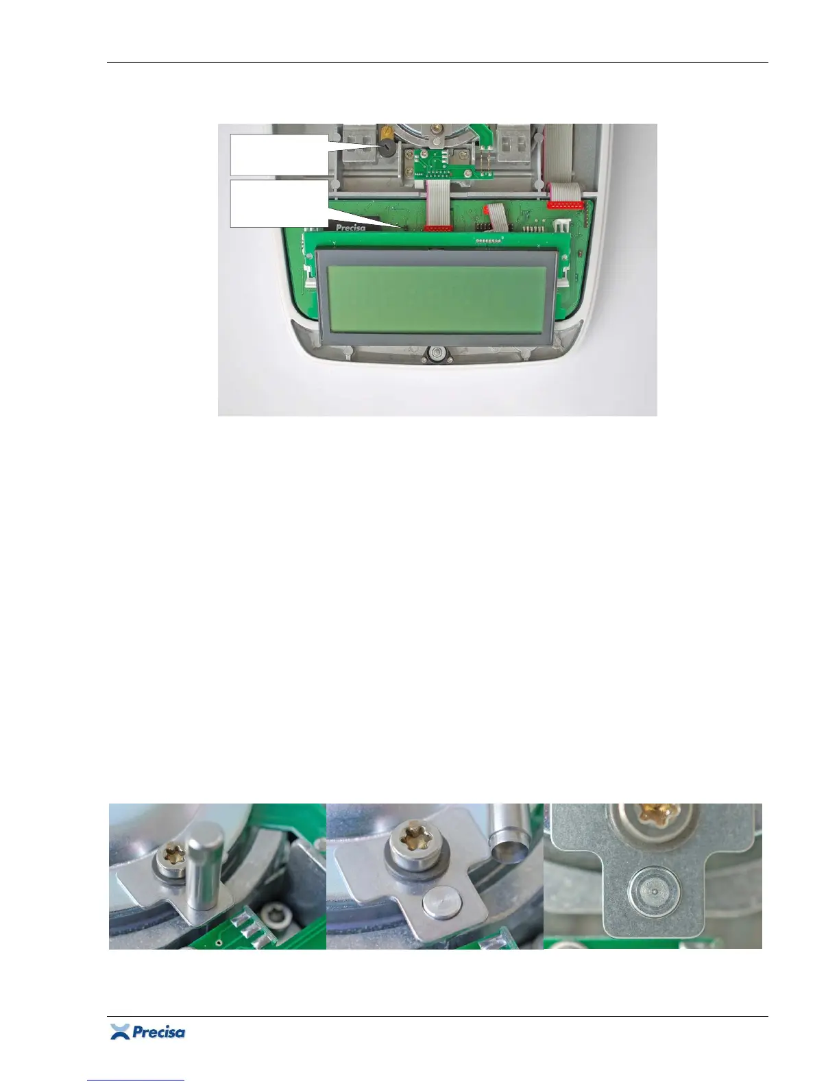
5. The voltmeter must show approximately the same voltage in both end positions of the balance
arm (once positive, once negative), if it doesn't, adjust the position of the balance arm with the
symmetry screw.
6. Detach the connecting cable with the voltmeter from the balance and latch the display board
again onto its holders on the main board.
3.4 Checking the pre-load
1. Ensure the balance is levelled and set to the factory mode according to chapter 3.2.
2. The pre-load error 60 (below minimal converter range) must not appear with placed weighing
pan without load.
3. The pre-load error 61 (above maximal converter range) must not appear with placed weighing
pan with full load.
4. If such an error is displayed, re-adjust the symmetry and ensure the balance arm does move
freely. It must not touch the transport safety device!
Symmetry
screw
Symmetry
pin header
S1