360 Adjustments
49
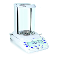
3.5.2 Adjusting the corner load (Group M/C/D)
Note:
Skip this chapter if the determined corner load values stay within the tolerated range.
• The difference of the diagonal A-C is adjusted with the left corner load screw 1.
• The difference of the diagonal B-D is adjusted with the right corner load screw 2.
• Turning the corner load screw clockwise
shifts the difference of the diagonal in negative
direction. The displayed value relatively decreases.
• Turning the corner load screw counterclockwise
shifts the difference of the diagonal in positive
direction. The displayed value relatively increases.
Procedure
1. Ensure the balance is levelled and set to the factory mode according to chapter 3.2.
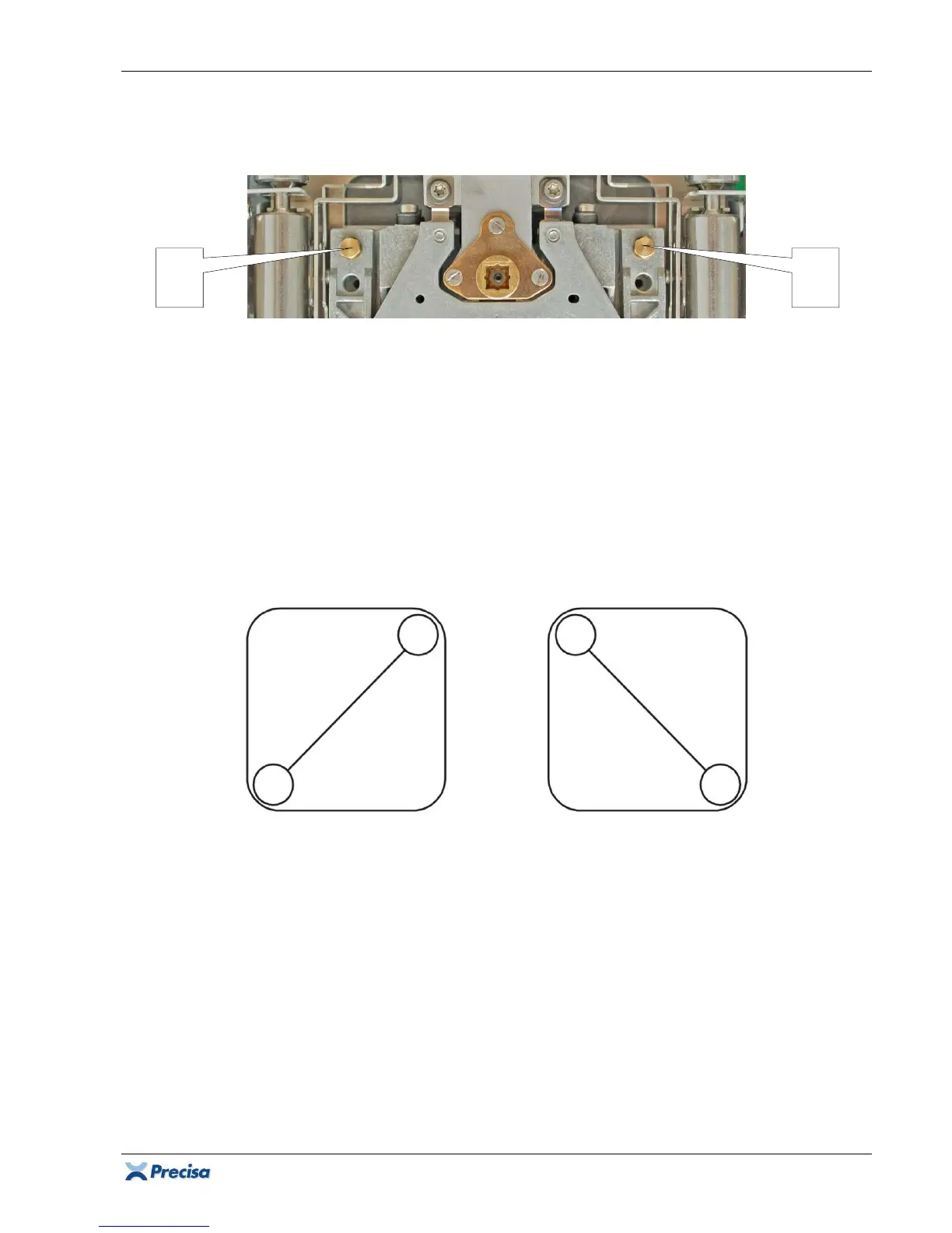
2. Place the weight on C, tare the balance, slide the weight to A and calculate the difference:
∆AC = A-C = A-0 = A [d]; (C = tared = 0);
Example:
∆AC = A = +12d.
3. Place the weight on D, tare the balance, slide the weight to B and calculate the difference:
∆BD = B-D = B-0 = B [d]; (D = tared = 0);
Example:
∆BD = B = -7d.
Important:
Start adjusting the diagonal with the larger difference!
4. The difference of the diagonal A-C is larger and positive (+12d). Turning the corner load screw 1
clockwise
shifts the difference in negative direction (+12 .. +11 .. +10 ..).
5. The difference of the diagonal B-D is smaller and negative (-7d). Turning the corner load screw
2 counterclockwise
shifts the difference in positive direction (-7 .. -6 .. -5 ..).
6. Keep reducing the diagonal differences, until all 4 corner load deviations stay within the
tolerated range (determined according to chapter 3.5.1, starting with step 4).
1