7 Operating Instructions
_____________________________________________________________________________________________________________________________________
7-7
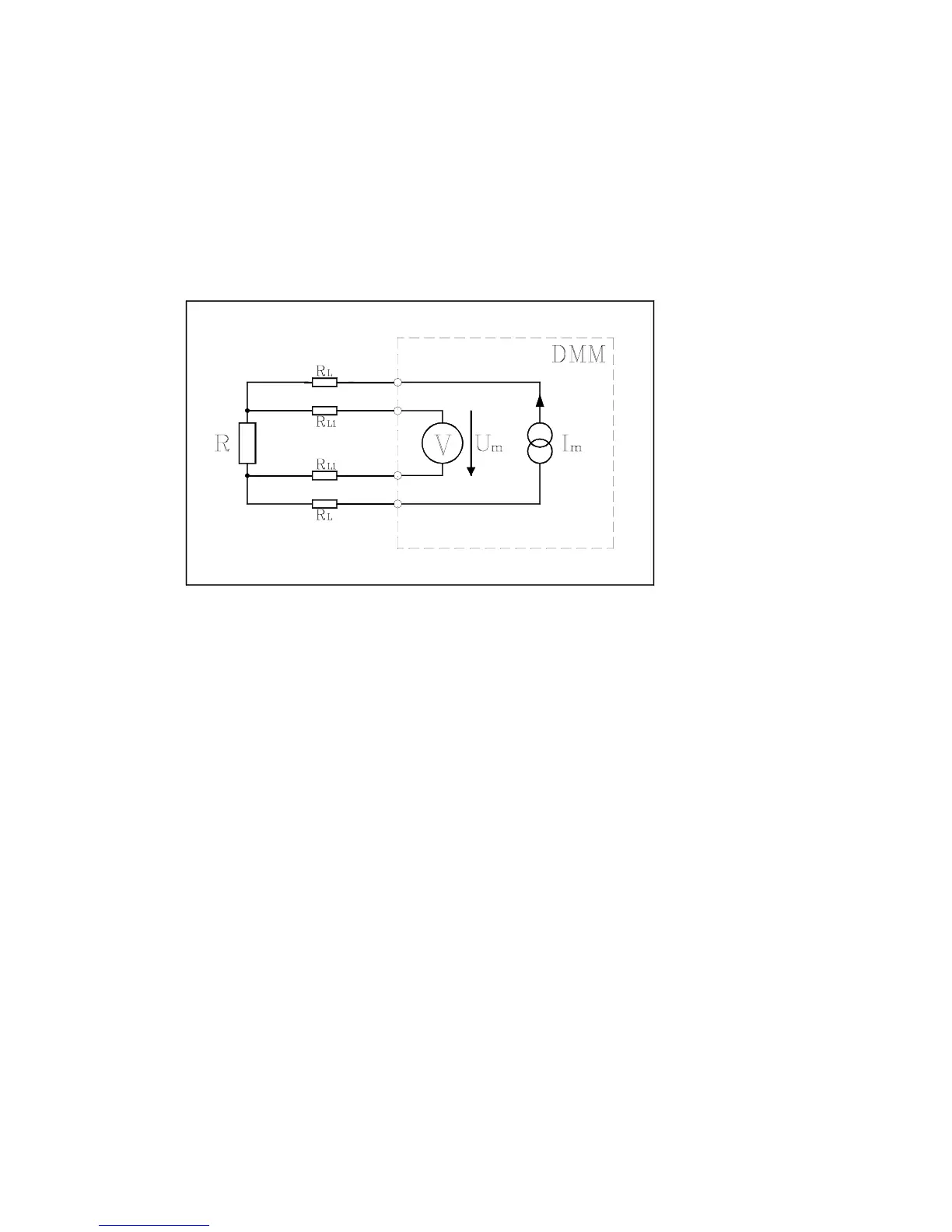
Four-Wire Resistance Measurement
To avoid the measurement problems that are produced by lead resistance, the four-
wire arrangement is used for the measurement of small resistances (see diagram be-
low).
Diagram: Principle of 4-wire resistance measurement
The measurement current I
m
is forced through the ‘external’ connections of four-wire
resistance measurements into the resistance R to be measured, through the cables with
the lead resistance R
L
.
The measurement leads with the lead resistance R
L1
are connected to the "Ω4W
Sense-Input" of the measurement unit, which possesses a high-ohm input stage, so
that a negligible voltage drop occurs at R
L1
.
The measured voltage is therefore to be considered as proportional to the resistance
value R.
ATTENTION !
In 2-wire, as well as in 4-wire resistance measurements, large resistances
(starting at 100kOhm) should be measured only with shielded measurement
leads, where the shielding must be connected to ground, to avoid noisy interfer-
ences through external voltages (e.g. Line Frequency).
The cables should have a very high insulation resistance (e.g. Teflon insulation)
otherwise leakage current problems may occur, because Rx and the cable insu-
lation resistance are connected in parallel.