Measuring Inputs
_____________________________________________________________________________________________________________________________________
4-6
The signal which is to be measured should always be connected in such a way that the
lead closest to ground potential is connected to the black input socket (LO) and the
line with the higher potential is connected to the red input socket (HI). The display
then shows a reading with positive sign.
Please read chapter ‘Getting Started’, "Connection of Measurement Leads" for
connecting the measuring cables for each measuring function.
The pinout of the measuring inputs of the measuring points scanner is specified in the
chapter "Technical Specifications".
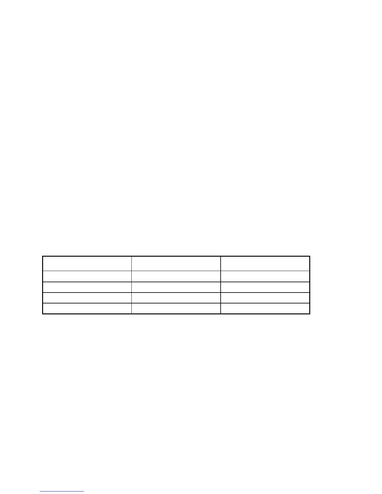
Limiting Data for the Measuring Inputs
The stipulated limiting data must be observed when connecting signals to be
measured. These limiting data are stated in red legend on the front panel adjacent to
the corresponding input connectors (Vpk means peak volts).
Measuring Input Front or Rear Sockets Measuring Points Scanner
V
Ω
- Hi-Lo
1000 Vpk 125 Vpk
Lo-Ground 250 Vpk 125 Vpk
Sense Hi-Lo 250 Vpk 125 Vpk
Sense Lo-Ground 250 Vpk 125 Vpk
Table: Limiting data for the measuring inputs