AC Voltage Measurement
_____________________________________________________________________________________________________________________________________
7-8
It is also of advantage to use an integration time greater than 1s, since the
greater length of measurement signal integration serves to suppress noisy scatter.
Power Dissipation in the Resistors
An error source that is often forgotten in the measurement of resistance sensors (e.g.
temperature sensors), is the power dissipation in the resistances to be measured, and
thereby the self-heating that is associated with it.
The measurement result can be strongly affected, especially with sensors that have
high temperature coefficients. A reduction of this error is achieved through appropri-
ate pre-selection of the measurement range.
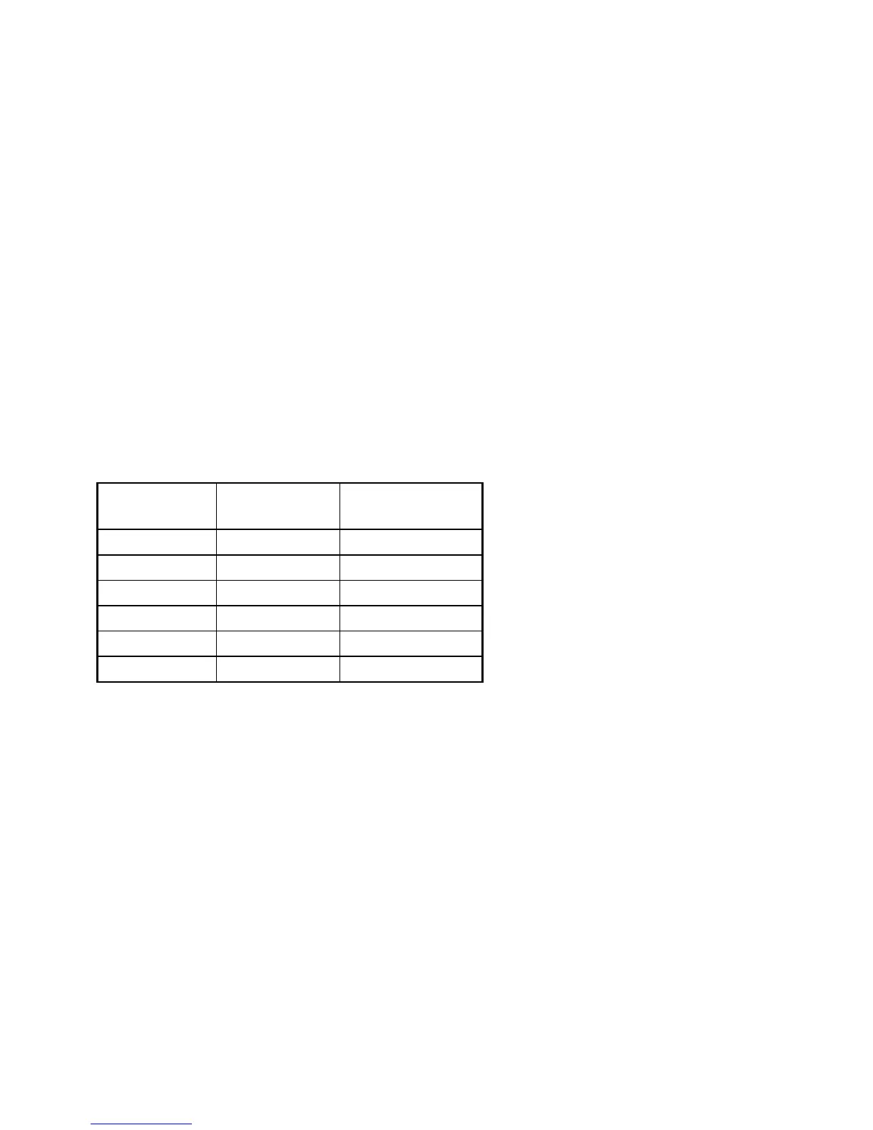
The following table provides an overview of power dissipation at the maximum
measurement value of each resistance range.
Range Meas. Current Power Dissipation
at Full Scale
300
Ω
1 mA 300 µW
3 k
Ω
1 mA 3 mW
30 k
Ω
100 µA 300 µW
300 k
Ω
10 µA 30 µW
3 M
Ω
1 µA 3 µW
30M
Ω
0.1 µA 0.3 µW
Table: Power dissipation on resistors
7.3 AC Voltage Measurement
The 5017 Multifunction Meter offers two methods of measuring AC Voltages:
• AC Voltage as True RMS Value with DC Component
• AC Voltage as True RMS Value without DC Component
The mode Vac+dc must be activated for AC voltages with a frequency lower than
50Hz. For AC Voltage measurements, it is recommended to use a two-lead cable with
shielding, with the shielding connected to ground.
Less shielding is achieved by using a simple coaxial cable.
 Loading...