2 Getting Started
_____________________________________________________________________________________________________________________________________
2-7
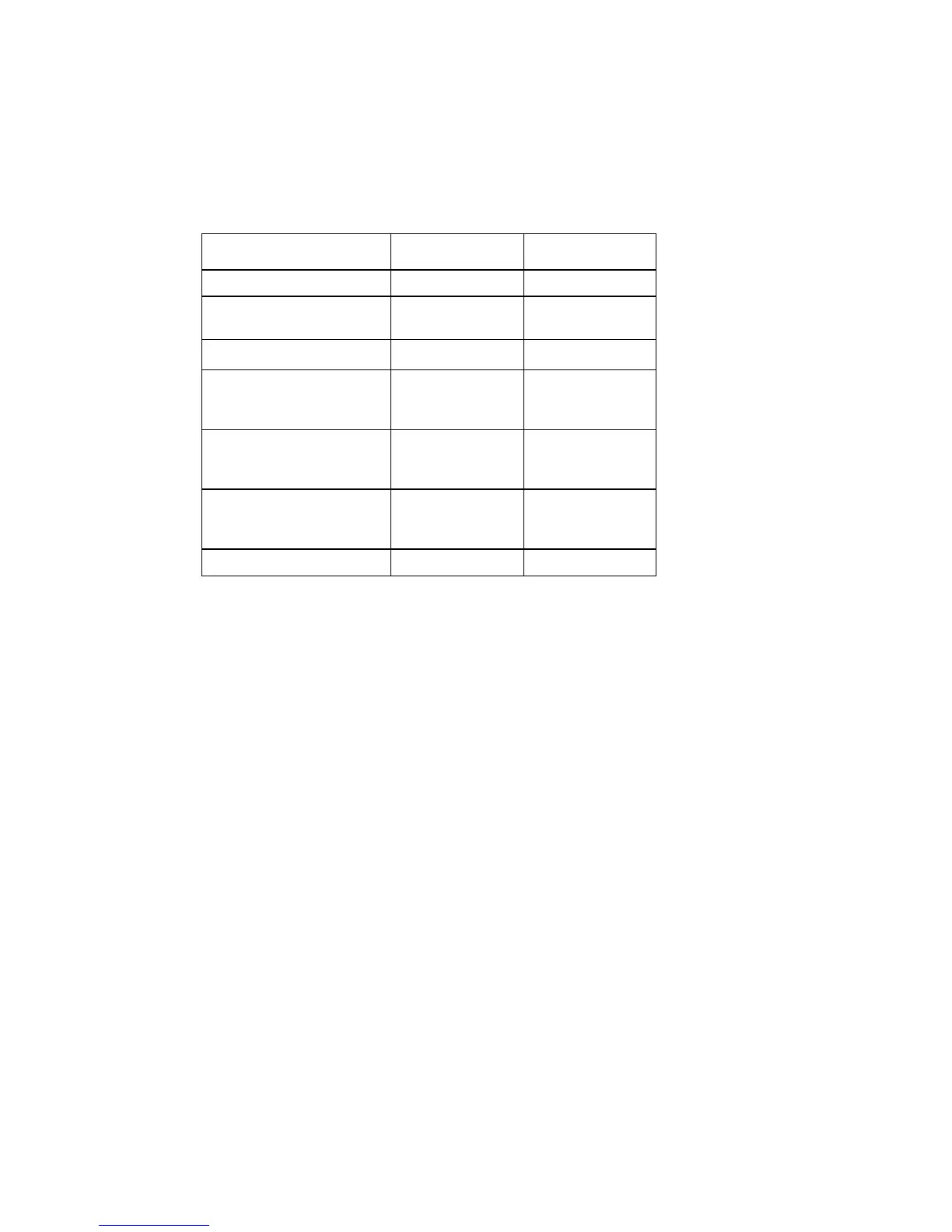
The following table gives information about the connection of measurement cables:
Measurement Hi Connector Lo Connector
DC and AC Voltage V-Hi Connector V-Lo Connector
DC and AC Current Amps-Hi Connec-
tor
V-Lo Connector
2-wire Resistance V-Hi Connector V-Lo Connector
4-wire Resistance
Source
Sense
V-
Hi Connector
Sense-Hi Conn.
V-
Lo Connector
Sense-Lo Conn.
Temperature with RTDs
Source
Sense
V-
Hi Connector
Sense-Hi Conn.
V-
Lo Connector
Sense-Lo Conn.
Frequency / Period
Voltage
Current
V-Hi Connector
Amps-Hi Conn.
V-Lo Connector
V-Lo Connector
Continuity Test V-Hi Connector V-Lo Connector
Table: Connection of Measurement Cables
In dealing with the Scanner option, please refer to chapter "Technical Specifications"
for information on measurement cable connections. There you will find a full de-
scription of the 50-line Sub-D connectors on the rear panel of the unit.