10. Screw the back part onto the control panel (using the PT
screws supplied).
11. Reattach the ribbon cable.
12. Position the front part in its parked position.
ð
First electrically wire the controller and then complete the
control panel installation.
13. Position the front part on the rear part of the housing and
screw the housing in place.
14. Once again check that the seal is seated properly. Degree of
protection IP 54 can only be achieved if it is correctly fitted.
4.3 Electrical installation
Put in place both hardware and software safety precautions to
ensure that the controller switches to a safe operating status in the
event of a fault. For instance, use limit switches, mechanical
locks, ...
Ensure that the controller is not energised during installation.
Make sure that the installation is only carried out by technically
trained personnel.
Observe the technical data in these instructions.
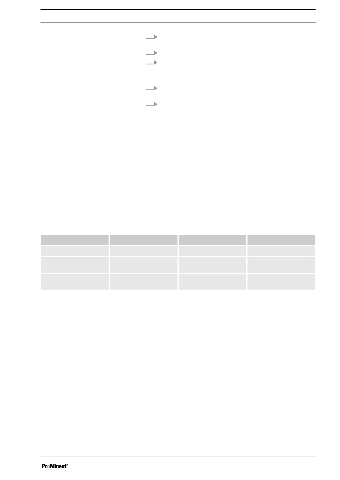
4.3.1 Cable Cross-Sections and Cable End Sleeves
Minimum cross-section Maximum cross-section Stripped insulation length
Without cable end sleeve
0.25 mm
2
1.5 mm
2
Cable end sleeve without
insulation
0.20 mm
2
1.0 mm
2
8 - 9 mm
Cable end sleeve with
insulation
0.20 mm
2
1.0 mm
2
10 - 11 mm
IP 54 degree of protection
Assembly and Installation
15