4.3.3 Connecting the terminals
There is also a field containing connection information next to the
terminals on the modules.
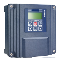
1. Strip the sleeve from the end of the cable as shown in Fig. 7
and press on the corresponding cable end sleeves.
2. To install the cables, push the screwdriver supplied right into
the square opening of the respective terminal to insert the
cable end into the terminal block.
3. Connect the cables according to the wiring diagram.
4. Check the cabling against the wiring diagram.
4.4 Primary Power Connection
AEGIS S has a switch-mode power supply. It can be powered by
an alternating voltage between 100 V and 240 V 50/60 Hz.
n Use a 3-point 1.5 mm2 cable for the power supply.
n Strip the 3 wires on 7 mm.
n Pass the 3-point cable through a cable gland.
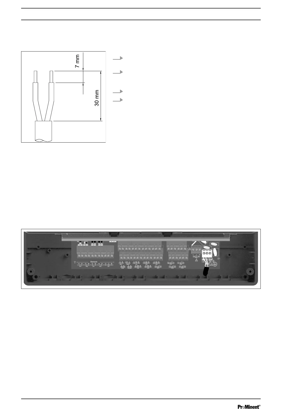
n Connect the phase on L1 and the neutral on the N of the main
terminal block X1.
n Connect the earth on the PL1 stud using an M4 eyelet terminal.
n Tighten the cable gland to seal.
Fig. 8: Primary power connection
AEGIS S does not have a main switch. It is therefore directly sup‐
plied with power when connected to the mains. It is therefore nec‐
essary to install a 10 A circuit breaker in front of the unit.
4.5 Connection of measuring inputs
n 1 Input RI1 RTD isolated for (Pt100 / Pt1000)
n 1 Input RI2 isolated for conductivity
n 1 serial sensor input for CTFS sensor
n 2 Inputs AI1 & AI2 4-20mA isolated for measurement of ph,
ORP, temperature, chlorine, bromine, etc.
n 5 digital inputs DI1 to DI5
Fig. 7: Stripping back the cable sleeve
Assembly and Installation
18