Connection of the sensor to AI2:
1. 1. Connect the sensor (+) strand to AI2 + (7).
2. 2. Connect the sensor (-) strand to AI2- (8).
3. 3. Tighten the cable gland to seal.
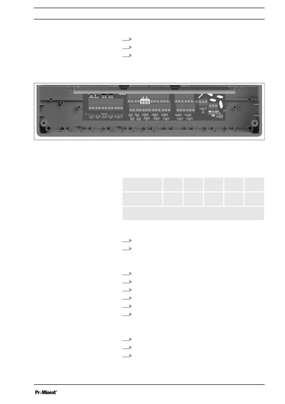
4.5.4 Digital inputs DI1 to DI5
Fig. 12: Digital inputs DI1 to DI5
AEGIS S has 5 digital inputs.
The selectable measuring ranges for volume are as follows:
0...20l/
min
0...50l/
min
0...200l
/min
0...10m
3
/min
Cus‐
tomer*
Volume
(impulses)
* A customized range can be defined between 0 and 2000 (L/
min, L/H or m3/H) in 4…20 mA or impulse input.
Connection of a R.I.C (Remote Input Control), tank bottom or
another sensor on DI1:
1. 1Connect one sensor strand to the DI1 sw (17) connection.
2. Connect the other sensor strand to the DI1 - (18) connection.
Connection of a flow switch sensor, e.g. to DI2:
1. Remove the protective sheath.
2. Strip the wires on 7 mm.
3. Pass the cable through the cable gland.
4. Connect the brown power strand to DI2 + (29).
5. Connect the blue power strand to DI2 – (31).
6. Connect the black contact strand to DI2 sw (30).
Connection of a flowmeter, e.g. toDI3:
1. Connect one sensor strand to DI3 sw (20).
2. Connect the other sensor strand to DI3 - (21).
3. Tighten the cable gland to seal.
Assembly and Installation
21