4.5.5 Serial input SI1
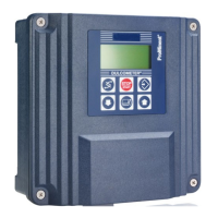
Fig. 13: Serial input SI1
Connection of a CTFS sensor on SI1:
1. Remove the protective sheath.
2. Strip the wires on 7 mm.
3. Pass the cable through the cable gland.
4. Connect the red power strand to SI1 + (9).
5. Connect the black power strand to SI1 – (10).
6. Connect the green contact strand to SI1 sw (11).
4.6 Self-powered relay PO1
The self-powered PO1 power relay output (Primary supply voltage
= Voltage available on P3) can be used to control the bleed valve.
A3761.
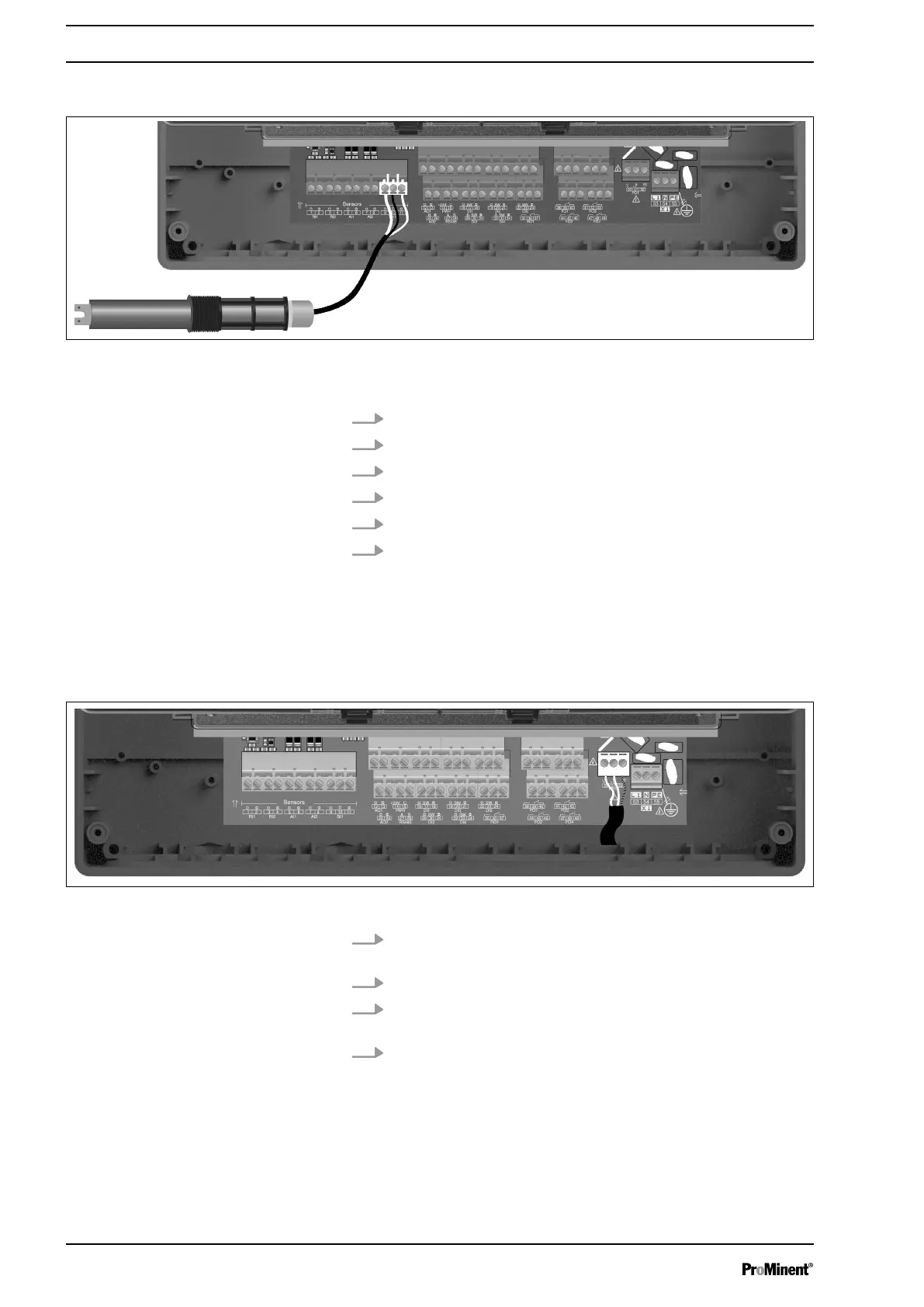
Fig. 14: Self-powered relay PO1
1. Strip the 3 wires of the power cable of the dosing device on 7
mm.
2. Pass the 3-point cable through a cable gland.
3. Connect the phase on L1 (50) and the neutral on N (51) of
the PO1 mains terminal block.
4. Connect the earth on PE (52) of the PO1 mains terminal
block.
4.7 Potential-free relays (FO1 to FO4)
The potential-free relay outputs can be used for the control of
dosing pumps.
Assembly and Installation
22